11

Although this may be a basic question but I'm still struggling with it. In this schematic, two zener diodes D1 and D2 are connected back-to back across relay coil L1. The BVds = -30V for Q1. Can I use 15V(Vz = 15V) zeners for D1 and D2 instead of 5.1 V zeners? Will the relay coil or contacts can get damaged during turn-off of relay? If required, I'm using this relay (5V DC Standard Coil).

Schematic

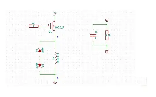
Also, to reduce steady state current consumption of relay coil, I wanna use the RC ckt shown aside in schematic. As soon as Q1 turns-on, uncharged capacitor temporarily appears as a dead short, causing maximum current to flow through the relay coil and closing the relay contacts without chatter. As the capacitor charges, however, both the voltage across and the current through the relay coil decline. The circuit reaches steady state when the capacitor has charged to the point that all the current through the relay coil is moving through R1. The contacts will still remain closed until the drive voltage is removed.

Which is the best place to put this RC ckt - section marked 'A' or 'B' in schematic. Will it make any difference? Section-B seems to me the best choice, as when Q1 turns-off, capacitor C1 can discharge via R1 through ground. How will C1 discharge when instead I place RC ckt at section-A? Am I missing something here? Does putting this RC ckt has any side-effects? Any better solution?

Please correct me if I'm wrong or missing something?

UPDATE1 on 2012-07-09 :

Say in above schematic I have 6V DC Standard coil(see datasheet above), 48.5 ohm relay. And take C1 = 10uF say. Assume that R1C1 ckt is placed at section-A in schematic above. The power supply is at +5V.

For a Drop of 3V(Hold-on voltage) across relay coil, the current must be 62mA approx. through coil. So drop across R1 at steady state is 2V. For a current of 62mA through relay coil at steady state, R1 must be 32.33 ohm.

And charge on C1 is 2V x 10uF = 20uC, at steady state.

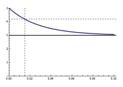
Now in this data sheet, the operate time is given to be 15ms worst case. From above data we have RC = 48.5ohm x 10uF = 0.485 ms. So, as soon as Q1 is turned on, the C1 will be almost fully charged in 2.425 ms.

Now how do I know that this duration of 2.425 ms is sufficient for relay to make its contacts close?

Similarly, as soon as Q1 is turned-off, due to back emf generated and clamped to 3.3V by zener D2(Vz = 3.3V) plus diode D1 drop of 0.7V, the voltage across C1 will be -2V + (-3.3V - 0.7V) = -2V. But charge on C1 is still 20uC. Since capacitance is constant, so charge must decrease as voltage across C1 decreased from +2V to -2V instantly after turning off Q1.
Isn't it violation of Q = CV?

At this point, the current that is flowing through relay coil due to back emf will be 62mA in same direction as was before turning-off Q1.

Will this 62mA current will charge or discharge the C1? The voltage across C1 is 6V as soon as Q1 is turned off right? I didn't get how currents will flow b/w R1, C1, D1, D2 and relay coil as soon as Q1 is turned-off.

Can someone throw light on these issues?

UPDATE2 on 2012-07-14 :

"Current in an inductor will not change instantaneously" - While there is a flyback diode D1(Say, D1 is not zener but a small-signal or a schottky diode, and zener D2 is removed in the schematic above), as soon as Q1 is turned-off, will there not even be a current spike(not even for few usecs)?

I'm asking this becoz, if there is a current spike then the amount of current that will flow during this spike(say > 500mA in this case) might damage the flyback diode if I had selected a diode with max peak forward current rating of around 200mA or so only.

62mA is the amount of current that is flowing through the relay coil when Q1 is on. So, will the current through relay coil never exceed 62mA - not even for a moment(say for some usecs) after Q1 is turned off?

jacks
  • 363
  • 1
  • 4
  • 12
  • @stevenvh- You mean to say RC = (R1 || Rcoil) x C1 ? – jacks Jul 09 '12 at 07:24
  • Yesssssssssssssss – stevenvh Jul 09 '12 at 07:26
  • Your latest edit (the 6 V across C1) isn't correct. The low side will go to -4 V, but the high side is floating, so it will go to -2 V. I explained in the edit in my answer that there doesn't flow any current to or from the capacitor, so its voltage can't change. – stevenvh Jul 09 '12 at 10:01
  • @stevenvh - so as soon as Q1 turns-off, the voltage across C1 will momentarily(for some usecs) go to -2V, and _then_ C1 starts discharging through R1. At this point there is a 62mA current through Relay coil, D1, D2 loop. The C1 will continue to discharge in this case(1500uF, RC = 48ms), even after the current through D1, D2 and relay loop drops to zero and relay contacts return to the rest position. I'll correct the edit('6V' across' C1). – jacks Jul 09 '12 at 10:13
  • 1
    If by "-2V" you mean that the high side is at -2 V, that's correct. But the *then* isn't. It doesn't matter much, as the time is really short, but switching off the FET causes the voltage change and *at the same time* C1 starts to discharge, since it was the current through the FET which kept it charged. The two processes of the C1 discharge and the coil's "discharge" (with everything that goes with it) are both caused by the FET switching off but happen *independently* of each other. – stevenvh Jul 09 '12 at 10:31
  • @stevenvh - That makes the things more clear. :) And, high side is at -2V and low side is at -4V momentarily, so this gives -2V - (-4V) = +2V _across_ C1. Isn't it? – jacks Jul 09 '12 at 10:44
  • 1
    Yes, but I would say "the low side is at -4 V and there's +2 V across C1, so the high side is at -2 V". It's the same thing, but it better indicates cause and effect. – stevenvh Jul 09 '12 at 10:52
  • @stevenvh - I do agree. – jacks Jul 09 '12 at 10:57
  • re your update dd 2012-07-14: no there won't be a current spike. Can't, the coil's inertia doesn't allow it. It has 62 mA, and that's what keeps flowing. When the FET is on it comes from there, when the FET is switched off D1 provides the closed loop needed for current. You can regard the coil as a flywheel where the speed is the current. If it rotates at 100 rpm it will never all of a sudden speed up to 1000 rpm for a few us. – stevenvh Jul 14 '12 at 06:42
  • @stevenvh - That clears the doubt. :) I have seen many tutorials that mention to add RC snubber circuits for relay _contact_ protection. Are flyback diodes are not enough? or, I need to add a RC snubber ckt at relay contacts along with flyback diodes across relay coil? or these RC circuits at contacts are to prevent spikes on load attached to relay contacts? – jacks Jul 14 '12 at 06:56

2 Answers2

10

You can place the RC either at the B side or the A side. When components are placed in series the order of them doesn't matter for the working.

About the diodes. When you switch off the relay it will cause a (possibly large) negative voltage on the FET's drain, and a flyback diode is used to limit that voltage to a 0.7 V diode drop. So the diode(s) don't serve to protect the coil, but the FET. Using the zeners will allow this voltage to go to -5.7 V or -15.7 V if you'd use the 15 V zeners. There's no reason for taking risks here, even if the FET can handle -30 V. So I would just use a rectifier or signal diode, or even better a Schottky diode.

edit re your comment
You can indeed use a zener (combined with a common diode, D1 doesn't have to be a zener) to decrease switch-off time, and Tyco also mentions it in this application note, but I don't read it as if they insist on it. The scope images in the first link show a dramatic decrease in switch-off time, but that measures the time between deactivating the relay and the first opening of the contact, not the time between first opening and the return to the rest position, which will change much less.

edit re the 6 V relay and the RC circuit
Like I says in this answer you can operate a relay below its rated voltage, and since its operate voltage is 4.2 V the 6 V version of your relay can also be used at 5 V. If you use a series resistor not higher than 9 Ω you'll have that 4.2 V, and then you don't need the capacitor (keep an eye on the tolerance for the 5 V!). If you want to go lower you're on your own; the datasheet doesn't give a must hold voltage. But let's say this would be 3 V. Then you can use a series resistor of 32 Ω and you'll need the capacitor to get the relay activated.

Operate time is maximum 15 ms (which is long), so as the capacitor charges the relay voltage shouldn't go below 4.2 V until 15 ms after switching on.

enter image description here

Now we have to calculate the RC time for that. R is the parallel of the relay's coil resistance and the series resistance (that's Thévenin's fault), so that's 19.3 Ω. Then

\$ 3 V + 2 V \cdot e^{\dfrac{- 0.015 ms}{19.3 \Omega \text{ C}}} = 4.2 V \$

Solving for \$\text{C}\$ gives us 1500 µF minimum.

Re switching off:
You can't violate Q = CV, it's the Law. Your clamping voltage is 3.3 V + 0.7 V = 4 V. That means that when you switch the FET off the low side of the capacitor momentarily will be pulled to -4 V, and quickly rise again to 0 V. The high side is 2 V higher, and will simply follow that 4 V drop while the capacitor discharges through the parallel resistor. The capacitor won't even notice the drop. The discharge time constant is 1500 µF \$\times\$ 32 Ω = 48 ms, then the capacitor will discharge to 20 mV (1% of its initial value) in 220 ms.

The 62 mA won't charge nor discharge the capacitor. We often apply Kirchhoff's Current Law (KCL) to nodes, but it also applies to regions:

enter image description here

Draw a boundary around C1 and R1, and you'll see there's only one path to the outer world since the way to the FET is cut off. Since the total current has to be zero there can't be any current through that unique connection. The coil has to take care of the 62 mA on its own, and it does so by using the loop formed by the zeners.

stevenvh
  • 145,145
  • 21
  • 455
  • 667
  • I understand those safety margins! Actually, BVds = -30V was just a refernce value. My intent to ask this question is to know whether are there any chances to damage 5V DC relay coil by placing 15V zener diodes across it, as during relay turn-off, the voltage across relay coil would be -15.7 V that could damage a relay coil rated for 5V? Isn't it? Take BVds = -50V say. – jacks Jul 08 '12 at 09:23
  • @jacks - max coil voltage isn't given in the datasheet but is usually 1.5 to 1.8 times rated voltage, so probably 7.5 V to 9 V here. A 15 V spike probably won't damage the coil, though I wouldn't allow it as a matter of principle: stick to the specs. One more reason not to use zeners. – stevenvh Jul 08 '12 at 09:31
  • So, in general if zeners are used across relay coil their Vz must not exceed Nominal coil voltage rating(5V in this case) + 1 ie Vz = 6V max. in this case, for saftey margins. BTW, some application notes from tyco and panasonic do insist to add a zener along with a normal flyback diode to speed up turn-off of relay and thus increasing contacts life. – jacks Jul 08 '12 at 09:37
  • Thanks for making thing clear :) Can I use TVS diode(Vrwm = 5.5V) here in place of zener D2? Does it make any difference? – jacks Jul 08 '12 at 10:35
  • @jacks - Yes, you can use a TVS. [This document](http://www2.microsemi.com/micnotes/134.pdf) explains some differences between the two. – stevenvh Jul 08 '12 at 11:28
  • Hmmm... I'll go through that doc. Just a confirmation; in my relay datasheet, does the term Operate Voltage means that for relay to hold its contacts close reliably, the _mininum_ voltage drop across relay coil must be 3.5V? or it means something else? Will operating at 3.5V decrease the relay contact or coil life? – jacks Jul 08 '12 at 11:55
  • @jacks - What does "hmmm..." mean? :-) Operate voltage is the minimum voltage to activate it. Once it's activated it requires a lower voltage, but the datasheet doesn't specify that. But that means that at 5V you can also use the 6V version, which saves you 25% of the power due to the higher coil resistance. In [this answer](http://electronics.stackexchange.com/a/34562/2064) I cover a number of ways to use a common relay more efficiently. The series resistor is one of the options, I didn't mention the capacitor, maybe I'll add it later. Operating at 3.5V is safe. – stevenvh Jul 08 '12 at 12:07
  • Thanks again, for this link. Very well written; though I couldn't get all of it but definitely it cleared many doubts. "hmmm..." resulted from chatting habits. :) How can I estimate the value of capacitance of C1, given say 6V DC, 48.5 ohm relay. Do i need to take into account the operate and release time of relay? – jacks Jul 09 '12 at 05:55
  • Well explained. :) This clears the turn-on situation. It would be nice, if you would clear the scenario during turn-off of Q1 too? Last 4 paras of my update section in question. – jacks Jul 09 '12 at 07:34
5

A relay may be modeled as an inductor with a significant series resistance. When the current in the inductor reaches a certain level, the contact will be 'drawn in'. When the current falls below a certain lower level, the contact will be released.

The reason flyback diodes are needed is that inductors behave, to use a mechanical analogy, as a "movable fluid mass". Just as it's not possible for a moving physical mass to stop instantaneously, and the amount of force generated by a moving mass when it hits something is proportional to the acceleration that thing tries to impart to the mass, so too with inductors. Current in an inductor will not change instantaneously, but will instead change at a rate proportional to the voltage across it. Conversely, the voltage across an inductor will be proportional to the rate at which external forces try to change the rate at which current flows through it. A device which tries to instantaneously stop the current in an inductor won't manage to stop it instantly, but will experience a voltage across it proportional to the rate at which it is able to slow it down.

The function of a flyback diode is to provide the current in the inductor with a path other than the transistor. The current is going to have to keep flowing somewhere, at least for a little while, and a flyback diode provides a safe path. The one limitation with a simple flyback diode is that it may allow current to keep flowing "too well". The rate at which current in the inductor will fall is proportional to the voltage drop across the inductor (which includes the voltage drop in the implied series resistance). The lower the voltage across the inductor, the longer it will take for the current in it to fall. Adding a zener diode in series with the flyback diode will increase the rate at which the inductor current will fall, and thus decrease the time before the relay switches off.

supercat
  • 45,939
  • 2
  • 84
  • 143
  • Got it. :) "Current in an inductor will not change instantaneously" - While there is a flyback diode(w/o zener say), as soon as Q1 is turned-off, will there not even be a current spike(not even for few usecs)? I'm asking this becoz, if there is a current spike then the amount of current that will flow during this spike(say > 500mA in this case) might damage the flyback diode if I had selected a diode with max forward current rating of around 62mA or so(eg 200mA) only. - 62mA is the amount of current that is flowing through the relay coil when Q1 is on. – jacks Jul 10 '12 at 12:22
  • 1
    There will not be a current spike when switching off an inductor, though in some situations the fact that current has to keep flowing *someplace* may, in the absence of flyback protection, cause it to take a path which would not normally have significant current flowing through it. It's worth noting that *mechanical* switch ratings need to be higher with inductive loads than with non-inductive loads, even when using flyback diodes, because mechanical switches can physically "draw" an arc in a way that solid-state switches do not. – supercat Jul 10 '12 at 14:52
  • 2
    Basically, what happens with mechanical switches is that at the moment the switch opens, the resistance starts to increases rapidly. Normally, this should cause the current flowing through the switch to drop to the point that it will not sustain an arc. If, however, one is switching an inductive load, current may continue to flow and sustain the arc as the contacts move further apart. If the arc is not extinguished while the contacts move apart, the voltage required to put enough current through the arc to sustain it will be *much* lower than the voltage required... – supercat Jul 10 '12 at 14:56
  • Thanks for clarification! This means that while selecting a flyback diode in this case, I need to consider only the 62mA(the current through relay coil when Q1 is on). => Any 200mA max forward current diode will work in this case, e.g. 1N4148, or even a schottky, as 62mA << 200mA. – jacks Jul 10 '12 at 14:58
  • 1
    ...to start an arc across the idle contacts. One way of thinking of that situation is to regard mechanical switches as having a brief moment on disconnect where their performance ratings are vastly inferior to what the spec would otherwise imply, and exceeding the specs at that moment may cause the device to "latch arced". So far as I know, however, such effects do not occur to any meaningful degree with solid-state switches; on the other hand, they can be destroyed by over-stress conditions which would only cause minor wear to relays. – supercat Jul 10 '12 at 15:00
  • I have seen many tutorials that mention to add RC snubber circuits for relay _contact_ protection. Are flyback diodes are not enough? or, I need to add a RC snubber ckt _at_ relay contacts along with flyback diodes across relay coil? or these RC circuits at contacts are to prevent spikes on load attached to relay contacts? – jacks Jul 10 '12 at 15:02
  • 1
    @jacks: I don't know what all is entailed when selecting flyback diodes. I understand that diode speed is sometimes important, but I don't know exactly how it affects things. As I noted, a higher voltage drop in the flyback loop can result in faster switch operation, though it will increase the amount of energy that is dissipated in the electronics rather than in the coil. Sometimes it is helpful to add a series resistor-capacitor circuit in parallel with an inductor, but there's a certain level of "black art" to picking the best values. – supercat Jul 10 '12 at 15:05
  • 1
    RC snubber circuits are indeed useful for protecting contacts, depending upon what type of load you are switching. I haven't really had much experience with relay-contact issues, except that I was playing with driving a 1960's pinball-machine score mechanism with relays and found that even with flyback diodes on the coils, the relays like to arc-latch on. – supercat Jul 10 '12 at 15:06
  • I do agree with you on "black art". I sometimes found these concepts mystical as there is no directly available info on such topics. Another such topic is power decoupling, bypassing and many more. – jacks Jul 11 '12 at 02:26
  • @supercat -- What do you mean by "arc-latch on"? – MicroservicesOnDDD Apr 06 '21 at 22:08
  • 1
    @MicroservicesOnDDD: The amount of current that would pass through a solenoid was sufficient to sustain an arc across the relay contacts even in the extreme open position. The relays wouldn't usually draw and sustain an arc, but I think they could have sustained arcs until the contacts were destroyed had they been allowed to do so. – supercat Apr 06 '21 at 22:26