I am designing a PCB which I will etch at home, but I need to know how to convert a wire gauge into the proper corresponding width of a copper track on the PCB. Is there a standard formula for this?
Asked
Active
Viewed 5,298 times
5
-
1possible duplicate of [Sizing a trace on a PCB to carry 2.5 amps](http://electronics.stackexchange.com/questions/8418/sizing-a-trace-on-a-pcb-to-carry-2-5-amps) – W5VO Jul 07 '12 at 01:46
1 Answers
5
There are formulas around to calculate current handling for various shapes/sizes of wire/trace, so rather than convert just calculate directly. There are various standards around (e.g. IPC2221 - was IPC-D-275 I think).
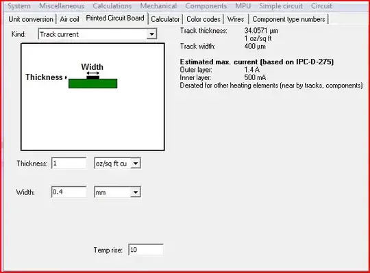
Rather than memorising formulas from the standards I think many use a tool of some sort. MiscEl is quite a useful little tool, amongst many other things, it has calculations for wires in AWG/mm/in/mil/etc - number of strands or solid core. For traces you put in desired width, temp rise and copper thickness and it will give you the max current for inner/outer traces.
Oli Glaser
- 54,990
- 3
- 76
- 147
-
Hi Oli--Can you please explain the "temp rise" field? Everything else makes sense, but I am not sure what this field is for, how to calculate the variable, or what unit it is in. Thanks! – Matt Cashatt Jul 07 '12 at 11:49
-
The temp rise field is the rise in the traces temperature with the max current passing through it. In the above picture the trace will rise by ~10 degrees when you have 1.4A (or 0.5A) passing through it. So you can e.g. set this to your desired maximum temperature rise. To see it from another other point of view, check the wires setting - you can set the dimension and the current and you see the temp rise for that current (plus advised max temperature) – Oli Glaser Jul 07 '12 at 12:05
-
FYI: I found IPC-2221 here: http://www.mcuexamples.com/Downloads/ipc2221.pdf – Jason S Oct 26 '12 at 17:35