6

I'm trying to display a 4-bit binary number on a 7 segment LED as a hexadecimal number (0-F). I have an assortment of 7400 series ICs including the 7447. But that one only works for BCD (0-9). The 7400 series doesn't seem to have a hex to 7-segment decoder and I don't have one on hand.

So I figure I'd have to build my own. The datasheet for a 7447 comes with the internal circuitry but I couldn't find a similar circuit for hex to 7-segment. I did K-diagrams for each LED segment by hand but the terms are rather large, much larger than for BCD.

Does anyone have a finished circuit for this that I can check my work against?

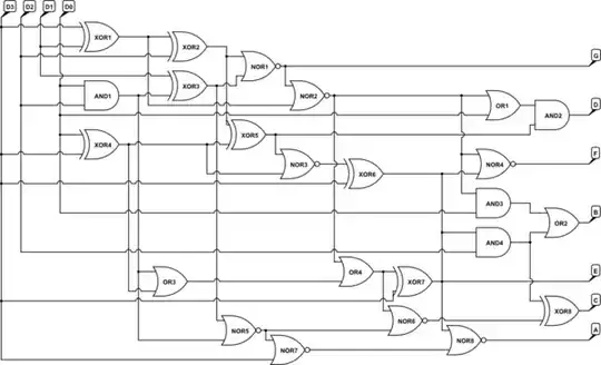
Does anyone have an optimized circuit for this that takes advantage of common subterms? There aren't many duplicate terms (like A0 & ~A1 & A2) but maybe using (A0 & A2) & ~A1 would allow sharing the (A0 & A2) subterm and overall reduce the gate count.

Or maybe some tricks to use NAND, NOR or XOR gates for some parts?

I don't care about different path length or races in the circuit as it's only going to drive LEDs and should be far too quick to see any of that.

  • 13
    I know it's not the right solution you're looking for but I'd recommend using an EEPROM such as AT28C16 or similar to convert the binary to hex. You'll just need to program the first 16 bytes. Connect the four binary numbers to be converted to the hex to the first 4 address lines and the data lines to the 7-seg pins. Program each byte of the first 16 bytes so that for address 0000 it lights up 0 on 7-seg display, for address 0001 it lights up 1 on the 7-seg display, and .... . Repeat this until you've programmed all the first 16 bytes. This can be done with a uC as well. – dirac16 Jan 23 '18 at 13:04
  • @dirac16, wouldn't you program the _last_ 16 bytes, and pull up the unused address lines? – Solomon Slow Jan 23 '18 at 15:02
  • @jameslarge Yes, you can. But I would program the first 16 bytes and pull down the other unused address lines. – dirac16 Jan 23 '18 at 15:43
  • I confess, my thinking still is shaped by the TTL era when all unused inputs were pulled high. – Solomon Slow Jan 23 '18 at 16:07
  • Quick question: On a 7 segment display, how do you intend telling the difference between `8,B` and `0,D`? The displays I have seen that were intended for hexadecimal have all used more than just 7 segments... – Baldrickk Jan 23 '18 at 16:18
  • 4
    @Baldrickk Hexadecimal on a 7-segment display uses lower-case for "b" and "d". You do then have a problem with "b" and "6" being similar, but "6" has the top segment filled in and "b" does not. (Based on the Casio FX-100D calculator which is on my desk in front of me right now.) – Graham Jan 23 '18 at 16:35
  • [Related](https://codegolf.stackexchange.com/questions/37648/drive-a-hexadecimal-7-segment-display-using-nand-logic-gates) – Digital Trauma Jan 24 '18 at 02:20
  • I am downvoting this question since even though I like the discussion, most of it is about generic logic design including CPLDs, microcontrollers, and PLAs. And even my answer, which I want to delete, involves just running an internet search ("hex 7-segment"), which implies my (unconscious?) opinion is that OP could have done more. – Lurker Larry Jan 24 '18 at 06:44
  • Indeed, I remember in one of my classes *30* odd years ago having such a hex display for programming a Motorola 6800 training board, so prior art exists, even if it missed the internet. – mckenzm Jan 24 '18 at 08:06

10 Answers10

15

Find what museum is missing their 74xx logic ICs and return them. Then get a small microcontroller and do all this in a single chip. As a bonus, you'll be ready for other advanced projects from the late 1980s and beyond.

Olin Lathrop
  • 310,974
  • 36
  • 428
  • 915
11

Maybe, if you feel particularly adventurous, you could even use a diode ROM, with perhaps two 74'138 3-to-8 line decoders to decode/drive the stuff. :)

A crude schematic Here's a crude schematic of the whole contraption; If you happen to use some highish efficiency LED displays, you may even be able to drive a common anode one directly.

The '!EN' pin can be either of the gate pins of the '138. You can also connect both of the other gate pins together, letting you turn the display output on or off as you please.

This also has the benefit over the suggested ROM solution that it's inexpensive to build/prototype if you have the parts on hand, or can't be particularly bothered to program ROMs.

Besides, one could even call this fun to make :)

Richard the Spacecat
  • 1,689
  • 15
  • 23
  • 1
    A 22V10 costs about $2 and can do this in one chip, but I admire your intrepidity. – stark Jan 23 '18 at 15:45
  • 2
    If you're even more adventuresome, it might be fun to work out a more "economical" approach if you're willing to put two diodes in series. For example, if one used two diodes for each "corner" to light up a top or bottom segment along with the adjoining edge (eight diodes), that would save two diodes from each of 0, 2, 3, 5, 8, one from 7, and one or two from 6 and 9 (depending upon the font). A simple diode ROM layout is probably easier to build, but working out a cheaper solution might be a nice puzzle. – supercat Jan 23 '18 at 17:30
  • 2
    The trick to use here is to program the dark segments, since there are fewer of them. Also use the '154 4-line to 16-line decoder. :) – Lurker Larry Jan 24 '18 at 06:07
  • 1
    1n4148 diodes cost 40 UK pence per hundred at Farnell. I remember making just this circuit. In 1975. – emrys57 Jan 24 '18 at 14:41
  • 1
    I like this. I would probably connect the outputs of the "ROM" to NOT gates to actually drive the LEDs. Otherwise for 8 you have to drive all 7 segments with a single output pin of an 74138. That would make it 4 ICs + lots of diodes. – Goswin von Brederlow Jan 25 '18 at 08:59
  • @GoswinvonBrederlow Yep, using NOT gates is basically _the_ traditional way to drive LEDs with TTL, afaik. Join that with Lurker Larry's suggestion, and you're good to go. :) – Richard the Spacecat Jan 25 '18 at 12:38
9

If you want to fiddle with gates, another possibility is to use a small FPGA or CPLD. You can get started with a flash-based FPGA for a few tens of dollars.

Reprogram it as many times as necessary to get it right, and you generally get a lot of I/O pins per dollar.

Example VHDL code here

For example, (shaky and not quite a complete loop, but you get the idea):

enter image description here

Spehro Pefhany
  • 376,485
  • 21
  • 320
  • 842
6

But that one only works for BCD (0-9).

Actually 7447 physically can accept hex values of A-F, but they display wrong images for them, see here page 3.

In my opinion, making hex-to-seven-segment decoder might be a good for education and visualization of how digital electronics work, but it is really bad idea from practical point of view - it is unnecessary complex and consumes much power in comparison to other solutions.

I recall having a PC diagnostic board back in ~1995 which was displaying error/status codes in hex (something like this), and this board used GAL chips - predecessors of CPLD.

If you have searched over internet for the solution, you might have seen a lot of similar projects using programmable logic or MCU-based devices like Arduino.

@dirac16 suggested another way - using parallel ROM chip, a kind of lookup table with bytes in it representing segments being on/off for respective address (input value).

Anonymous
  • 6,908
  • 1
  • 14
  • 41
6

MC14495, DM8880/9368, V40511, D345, D346, 4311, 4368 or 74C915

All of these are hard to get your hands on nowadays.

Janka
  • 13,636
  • 1
  • 19
  • 33
  • I saw a reference to the MC14493 doing hex to 7-segment, but I got frustrated while looking for a datasheet. But it was available for 8.75 EUR in single quantities. I am scared that it is only bcd though, so I would find that datasheet first. – Lurker Larry Jan 25 '18 at 18:12
  • 2
    74C915 is a 7-segment to BCD converter. So wrong way and only BCD not hex. Strange chip to make. – Goswin von Brederlow Jan 29 '18 at 11:34
  • 1
    Ah yes, you are right. But I know a use case for such a chip: stamped scales. They require the customer sees the correct weight, so law may require you to convert the visible output back to BCD if you ever wanted to connect a printer. – Janka Jan 29 '18 at 12:57
  • @LurkerLarry MC14495 is still available on eBay, $1.50, and here is the [datasheet](http://www.riana.com/electronics/docs/MC14495.pdf). I've bought a couple recently, no problem experienced. – Greenonline Jul 07 '18 at 20:16
5

I think I have managed to find the optimal solution (one of them) now. It uses all 24 gates of 6 ICs:

  • 2x 7486 (quad XOR)
  • 1x 7408 (quad AND)
  • 2x 7402 (quad NOR)
  • 1x 7432 (quad OR)

I've managed to find different solutions using only 23 gates but more ICs. I have a feeling there isn't a solution with just 5 ICs.

Note: The circuit outputs LOW when the LED should be on since my 7 segment LED has a common VCC.

schematic

simulate this circuit – Schematic created using CircuitLab

D3-D0 are the inputs with D3 being the MSB. A-G are the outputs with A being the top LED, then going clockwise around and last G being the center LED.

  • Have you considered something like the 74HC157 [2-channel 4:1 multiplexer] or possibly an inverting variant thereof? It might have been nicer if there were a variant which traded off the enable outputs for separate left/right selection inputs, but such chips can be really handy sometimes. – supercat Apr 20 '18 at 20:58
  • Only as an alternative to a diode rom but you need too many of them. You could use them as programmable gates but each multiplexer would have to replace 2 gates to draw even. – Goswin von Brederlow Apr 21 '18 at 14:52
3

If you want to design the functions by hand an check them for correctness before (or instead of) implementing them in hardware, you can use an online calculator like this one.

There are also tools which can minimize multiple logic functions sharing common inputs. One is expresso, which has free implementations in Windows and Linux.

Dmitry Grigoryev
  • 25,576
  • 5
  • 45
  • 106
  • 2
    This really sounds like a comment offering supporting advice, not an answer. – Chris Stratton Jan 23 '18 at 19:08
  • 2
    @ChrisStratton Frankly I don't see the benefit of posting the actual solutions here. – Dmitry Grigoryev Jan 23 '18 at 20:22
  • 1
    That calculator only solves one output at a time and shows only one solution even if there are multiple. That means it can give solutions that have less terms in common between the outputs. I.e. use more gates than necessary. – Goswin von Brederlow Jan 25 '18 at 09:06
  • @GoswinvonBrederlow Good point, but it's a matter of search to find a logic optimizer which does what you want. – Dmitry Grigoryev Jan 25 '18 at 10:08
  • @DmitryGrigoryev I've searched before and I have never found a free logic optimizer yet that does more than just transform the POS or SOP to use different gate types. Nothing that actually optimizes. It's a NP hard problem I believe and quickly takes to long to find the optimal solution. So people don't try. It quickly becomes simpler to use a rom as lookup table (as suggested above). – Goswin von Brederlow Jan 25 '18 at 15:09
  • According to the man page, espresso does optimize, though it uses heuristics to simplify the task. – Dmitry Grigoryev Jan 25 '18 at 15:20
  • I tried Logic Friday (one of the tools listed as using espresso) before and it wouldn't optimize for the available gates. It seems to find a minimal form using espresso and then converts/expresses that minimal form using the gates you select. That is fine if you want only NAND or AND+OR. But if you have AND+NAND+OR+NOR+XOR it doesn't see a need to transform anything and won't use the extra gate types for a more optimal result. – Goswin von Brederlow Jan 29 '18 at 11:48
1

It's been said you can try the ICM7218 or some other chips.

You may also try to build your own combination circuit. This is a great video tutorial on how to do it and its mechanics. If you want to optimize it, there are some datasheets (1, 2) with the BCD (0-9) part.

As a follow-up, this guy also made a follow-up video on how to do the same with an EEPROM. Granted, you still have to program it, but it may be worth it.

And talking about programming, you may also do it all with a microcontroller. It is usually easier to program than a CPLD (which you may also use), and there are both code and tabular implementations. I'd use this option, since I'm familiar with microcontrollers (you're not limited to the Arduino) and for just the chip it might even be your cheapest option.

Ronan Paixão
  • 1,015
  • 6
  • 7
1

Use Google to find "hex 7-segment" items, including http://en.wikipedia.org/wiki/Seven-segment_display which has a hex truth table (in hex!). Other items include diagrams and video demonstrations.

I was actually looking for four-digit, seven-segment displays that do the hex decoding for you, but they are considered to be "ancient" (sniff) and modern ones use i2c rather than parallel interfaces.

Lurker Larry
  • 111
  • 1
  • And 95% of the results actually talk about BCD to 7 segment, 4% have no circuit but just truth tables and such and 1% are videos where you can't make out what is supposed to be an and gate or or gate. – Goswin von Brederlow Jan 25 '18 at 08:47
  • Perhaps then I should have just posted this link https://youtu.be/7zffjsXqATg and said that the circuit you requested is at 12 minutes in and his TTL implementation is shown 30 seconds later. His part list is in the description. I sincerely apologize for not taking into account that search engine results are not predictable. – Lurker Larry Jan 25 '18 at 17:42
  • Yeah, that's the 1% in the search that actually applies, the "videos where you can't make out what is supposed to be an and gate or or gate". I looked at the circuit again and it uses 49 AND and OR gates. https://codegolf.stackexchange.com/questions/37648/drive-a-hexadecimal-7-segment-display-using-nand-logic-gates on the other hand has a solution with 37 NAND gates. So far that's the winner. – Goswin von Brederlow Jan 29 '18 at 11:55
0

I've been using the DM9368N for that purpose for years now, and it's reasonably easy to get (15$ for a 10-pack on ebay or Aliexpress).

WooShell
  • 267
  • 2
  • 6
  • This device has exactly the logic required for the job, but look out for the supply current! – user131342 Jan 25 '18 at 11:03
  • @henros Of course, this chip is designed for driving an LED display directly.. you can not use it just as a decoder to forward into further logic. – WooShell Jan 25 '18 at 12:49