0

I am getting crazy with a board intended to drive an AC induction motor, which has two symmetrical windings (for the two run direction), a center tap, and requires a run capacitor.

The motor is rated about 900 watts, it can draw maximum 5 amperes, but until now I used it with no load, so 1-2 amperes are consumed.

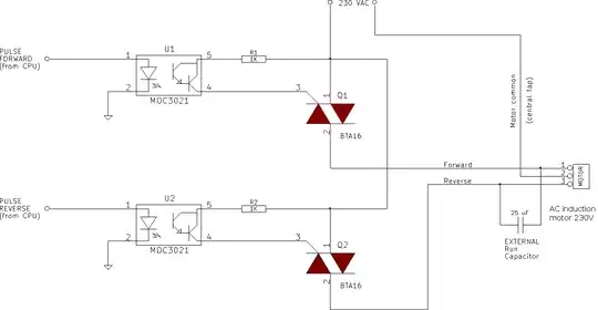
The idea is to drive a single TRIAC at a time, in the usual way, modulating the pulses in order to control the speed (a rotary encoder provides feedback). Just to be clear, speed control/braking/reverse work well, my problem is that the board is not reliable, the TRIACs melt quickly even without big solicitations, but when they are sane, the results are good.

The schematic is the following:

schematic

By driving one or the other TRIAC it is possible to command the running direction, and also decelerate (when pulsing the TRIAC opposite to the running direction of the motor).

The circuit works as intended, but is very fragile. If the system is powered with low voltage (30 volts AC), everything is smooth; if the system is powered with the intended voltage (mains 230 VAC), it survives tens of seconds and then fuses blow and TRIACs burn.

If I mount only one TRIAC everything works well (of course, in one direction only): it does not burn. Mounting the second TRIAC, the opposite tap of the motor is no more free but it is connected to the circuit. Apparently the opposite tap develops high voltage and spikes which need to be canceled.

I used an oscilloscope to analyze what was happening: I was looking for cross excitation of the TRIACs, extra voltage spikes and so on. Everything seems normal, but the TRIACs keep to blow up. They are rated 800 volts. I then tried to protect them using two 750V varistors in parallel to the anodes. The varistors heat a lot, and this suggests me that there are high voltages running around, even if I don't see them with the scope.

The next move has been to use 1.2KV rated TRIACs (don't have the part number at hand now). Things go slightly better, but when the TRIAC angle, from "low" power (near to right right end of the semi-cycle) is increased to more power (near the middle of the semi-cycle), the TRIACs blow again. Fuses blow also, but no other components are affected. My thought is that first a TRIAC fails (or two TRIACs fail), then the short-circuit blows the fuse.

When the board fails, it seems that both the TRIACs melt, but I am not very sure of this - I mean, until now I've never seen a single TRIAC blown, always two.

I think I am missing something: to blow a 1200 volt rated TRIAC, a 1200 volt voltage is necessary! I understand that windings can develop high voltage, but I can not see it.

I tried to power that part of the board with 21 VAC (rms) from a transformer. The resulting sinusoidal wave has 67,2 volts peak to peak. The motor runs in the expected way (of course with very little torque). In no way I can see any voltage over 88 volts between any 2 points of the circuit. A pretty high voltage (peak to peak) is found across the motor capacitor: it can be as low as 44 volts with "low power" TRIAC angles, up to 85 volts (peak to peak) when exciting a TRIAC near the middle (top) of the semi cycle.

Calculating some proportion: if instead of 21 VAC, I use 230 VAC, then I should have around about 800/900 volts peak to peak. They would not be sufficient to burn the 1.2KV TRIACs, but it happens!

I don't know what to do. Somebody can help me please? Thanks, (many) thanks in advance.
  • 1
    What is connected to the motor? Some machinery with lots of intertia? – filo Jan 23 '18 at 11:19
  • @filo there *will* be a lot of inertia, but for the moment the motor runs mostly free. It is connected to a gear - with no load it takes up about 1A. – linuxfan says Reinstate Monica Jan 23 '18 at 11:27
  • 1
    I don't see any snubbers. The dv/dt across the second triac could be exceeding the trigger dv/dt. They both come on and you get a huge current surge. Current is what kills a triac. – lakeweb Jan 23 '18 at 16:55
  • @linuxfan Did you solve you problem ? – rom1nux Nov 29 '19 at 01:06
  • @rom1nux yes, it seems (thorough testing is still needed). The solution is a combination of high voltage triacs AND optotriacs, snubbers, and care to not cross-excite both the triacs when inverting direction. – linuxfan says Reinstate Monica Nov 29 '19 at 09:48
  • @linuxfan It's possible to get more info on your project ? I try to do a (more simple) [control speed motor](https://electronics.stackexchange.com/questions/469183/help-for-triac-strange-behavior) (like yours symetrical+permanent cap) and got several problem with the power stage (Triac+MOC+ZCD) I got glitch and bad signal. I'm interested by your component value, ZCD filtering, etc... thanks in advance – rom1nux Nov 29 '19 at 10:45

7 Answers7

1

Can you add more details about the PWM driving? min /max duty cycle and frequency? Also: -disclaimer no experience with triacs but many experience with power mosfets- Did you measure the triacs after failure? With mosfets, overvoltage failure usually shorts gate to source, while thermal failure only shorts drain-source.

Possible overvoltage causes are caused by inductance as you imagined, thermal problems can be caused by ringing.

The advantage with fets is that you can play with gate resistance (hence dV/dt of output) which you can't do with triacs. But you could try snubbers to see if it makes a difference.

gommer
  • 1,023
  • 6
  • 17
  • It is not a PWM driving (not possible with triacs), but a phase shifting driving (exciting pulse located in variable places in time). The TRIACs are snubberless ones. When blown, the triacs are cold; sometimes the anodes are shorted, often the gate too. The snubbers can be a good idea anyway, but I suspect I am missing still something else. – linuxfan says Reinstate Monica Jan 23 '18 at 11:31
  • False (parasitic) triac triggering maybe? As you mention that when mounting only one triac the board runs fine. – gommer Jan 23 '18 at 11:52
  • may be, even if I didn't see it with the scope. With 1.2KV the situation is better, and this seems to exclude a parasitic triggering. I am still collecting advices from you all. Thanks. – linuxfan says Reinstate Monica Jan 23 '18 at 13:46
  • Snubberless means "higher dv/dt to trigger than normal triacs", but snubbers are also to dampen turn-off ringing which can cause overvoltage failure. – τεκ Jan 23 '18 at 14:42
1

When switching off your motor is acting as a generator. The triacs try to block current, which leads to voltage spikes.

A very safe solution is to add a braking circuit. I've tried that with motors blowing up VFDs used with long conveyor belts (lots of inertia) - the motors were pumping supply above input voltage and above max voltage of the VFDs. When you switch off the triac you have to connect a resistor [bank] across your winding to safely dissipate the power. This will prevent energy blowing up your triac. You can try different resistor values for different braking speeds.

Of course you can try a "bigger", more expensive triac, but braking may be more cost effective depending on your exact machinery.

filo
  • 8,801
  • 1
  • 25
  • 46
  • Uhm... I think it is different. The Triac switches off "naturally", when the current falls to 0 (it is impossible to switch them off earlier). In fact, the resulting wave is reasonably clean. Moreover, the failure does not happen when "braking", it is sufficient to simply run the motor. – linuxfan says Reinstate Monica Jan 23 '18 at 13:50
  • 1
    Yes. It switches off and goes to blocking, but it can only block until its breakdown voltage. The energy must go somewhere. – filo Jan 23 '18 at 14:08
  • I understand, but the new triacs are rated 1200 volts (voltage I've never seen around). There must be something related to what you are saying about breakdown, especially on the opposite tap of the motor (the one not driven). But how is it possible to heat varistors without seeing anything on the scope? – linuxfan says Reinstate Monica Jan 23 '18 at 14:19
  • Remember that triacs also have a dv/dt limit (how fast the voltage can rise and not blow up the device). – filo Jan 23 '18 at 16:54
  • 1
    @linuxfan Why do you think the voltage isn't going up to 1200 volts? I'm not familiar with mains voltage motors, but when switching off a 5V coil without a snubber you can get 100V+ spikes - it's not implausible that on 240V you could get 5000V+ spikes. – user253751 Jan 24 '18 at 06:14
  • @immibis Because TRIACs turn off (automatically) at zero current, which is a very different situation from your example. And because mounting only one TRIAC everything is fine. When mounting the second TRIAC, even without driving it, problems arise. What is the difference? Is that the opposite pole of the motor, once free, now is connected to the circuit. Hence, it is THAT opposite pole that develops spikes, not the driven one. – linuxfan says Reinstate Monica Jan 24 '18 at 06:21
  • @linuxfan Yes, the TRIAC turns off automatically at zero current. And then the motor's inductance continues trying to force the current through it which can produce a voltage spike of up to 5000 volts (estimate). This is also how boost converters work. – user253751 Jan 24 '18 at 06:23
  • @immibis no no, direct current is different from alternate. I work all the day with AC motors driven by *single* triac. No snubbers, no MOVs, no problems. This is the first time I try to put *two* TRIACs to the two legs of the motor. Only one leg has no problem. The other leg can develop spikes because the two motor windings are coupled, and because there are at least two phase shifts (two coupled windings and a run capacitor)... it is a mess. So I really need to cancel extra voltages from the *other* leg - as the circuit is symmetrical, you are not entirely wrong. – linuxfan says Reinstate Monica Jan 24 '18 at 06:31
1

If it's an AC induction motor, which it sounds like from your description, you can't expect to reliably control the speed this way (there are exceptions for tiny motors < 100W, in ceiling fans or HVAC pumps).

You need to control the AC frequency : the controller you need is a Variable Frequency Drive. (Most of these are designed to control 3 phase motors; you need one that can drive a single phase (or split phase, that's what the capacitor is for) motor.

1

You may be using 'snubberless' triacs but you still need to include a snubber to keep the voltage within limits when driving an inductive load.

see section 1.2 of this app note: http://www.st.com/content/ccc/resource/technical/document/application_note/38/88/44/b8/2c/26/44/b8/CD00004096.pdf/files/CD00004096.pdf/jcr:content/translations/en.CD00004096.pdf

τεκ
  • 4,229
  • 1
  • 16
  • 17
0

At 230V and standstill of the motor, you have a gate current of 230mA to the triac. Peak gate current is 4A for the BTA16, but it's better not to overstrain this. 100mA is sufficient in all cases.

Janka
  • 13,636
  • 1
  • 19
  • 33
0

In addition to adding a snubber circuit as suggested by @TEK, you should prevent switching directions without some off time in between. You don't need to wait for the load to coast to a stop, but you should allow time for the motor's magnetic field to diminish. My guess is that 150 to 500 milliseconds would be sufficient.

Reducing the voltage as a means of speed control is actually reducing the torque capacity of the motor. Look at my answer to this question for additional information. There you will see why this method of speed control is usually used only for fan and centrifugal pump loads. It can be used for constant torque loads over a very limited speed range, but there will be a risk of overheating the motor. The motor will tend to stall if the speed is reduced too much.

Since speed reduction is achieved by reducing the motor's torque capacity thus allowing the load to make the motor slow down, there will be little or no speed reduction at no load or with a very light load.

  • Thank you for your answer. My problem is not related to speed control, or "switching direction without off time in between". Everything is OK when the TRIACs are not broken. The problem is that the TRIACs burn, even without big solicitations. I need a way (probably snubbers) to reduce spikes, avoid parasitic triggering, protect TRIACs and make the board reliable. With the new 1200V TRIACS the board seems OK @230V AC, but I am not satisfied because I know I am on the edge, and I can not trust that the 230V mains are always clean and stable. – linuxfan says Reinstate Monica Jan 24 '18 at 05:50
0

Not sure if you were able to resolve this problem. I had a similar problem and was a able to solve it by adding a 4.7mH inductor in series with the Triac connection to the motor. I don't think you need such high ampere triacs.

  • Thank you Manish, I did too think at an inductor, but I wasn't sure. In the meanwhile, I made some progress by using triacs and optocouplers with higher voltage rating. Due to the motor+capacitor, the voltage can rise up to 1200 volts... – linuxfan says Reinstate Monica Jul 17 '18 at 16:53