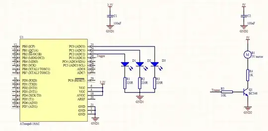
Everything in your circuit needs a common reference. That's the circuit's ground. You can compare the separate grounds and the trigger to the following: take two batteries, and connect the + of the first one via the 10 kΩ resistor to the - of the other one. There won't flow any current through the resistor since, as Alfred says, there's no closed loop.
So for driving Q1 you need a current path starting at the +3.3 V through the microcontroller, R5 and Q1 to ground, and that should close the loop, so connect that ground to the - of the 3.3 V. It doesn't matter that this is also the ground for another supply voltage; if you have two separated circuits you can always choose one point on each of them to connect them, and that's usually their grounds.
Alfred mentions optocouplers and we discussed them in other questions. There you have two separate grounds because you have two separate circuits. There's an optical but no electrical connection between the 230 V AC side and the 3.3 V DC side, and there's no need for current to flow from one side to the other. Same with transformers. There we have a magnetic connection, again no electrical.