24

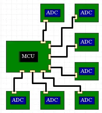
I currently make a system consisting of a plastic enclosure which contains an MCU talking to 7 ADCs using 2MHz SPI over wires about 5cm long.

MCU and ADCs connected by SPI

The problem is that I'm concerned about EMI. Everything I have read suggests that any kind of digital signal that's not safely on a PCB in a grounded metal chassis will radiate too much to pass EMI testing. I guess this would include I2C as well.

Is this likely to fail EMI testing? What can I do about this?

I am looking for any kind of answers, including "Use a different bus / ADC", but not including answers that involve mechanical changes like: "Put all the ADCs on the same PCB" or "Put the whole thing in a metal box". I am especially interested in Low-EMI alternatives to SPI including differential buses.

Here is some relevant information about the application. Please let me know if you need to know more things:

  • 6 wires go to each ADC board (Power, GND, CS, CLK, MOSI, MISO).
  • ADCs are currently MCP3208 (Microchip 8-channel, 12-bit)
  • I am working in a desperately space constrained application, so adding shielding to the wires isn't really an option.
  • It would be nice to use some kind of differential bus (one or two pairs only), but the only ADCs with differential communication seem to be multi-MSPS LVDS types.
  • CAN is probably too slow, and also kind of bulky for such a space constrained application.
  • Sample rate: I need to sample every channel at 1kHz.

Added:

Just to give an idea of the space constraints:

Small PCB with MCP3202

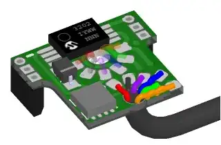
Here you can see one of the ADC PCBs. This one actually has an MCP3202 instead of an MCP3208, but it's compatible(ish). It's in a TSSOP 8 package. The PCB is 11mm x 13mm. The black cable is 2mm diameter. As you can see, there isn't even space for a connector and the wires are soldered directly to the PCB, then potted. The lack of connector is due to surrounding space constraints rather than PCB space constraints.

Rocketmagnet
  • 26,933
  • 17
  • 92
  • 177
  • 4
    How can shielding the cables be considered impractical but doubling the number of wires (differential signaling) be considered practical? – timrorr Jul 05 '12 at 12:42
  • Sorry, I should have been more clear. I meant something like CAN, which is 2 wire differential. Obviously doubling the number of wires is impossible. I have edited the question. – Rocketmagnet Jul 05 '12 at 13:01
  • 1
    Specifically, what type of testing/certification are you trying pass? – Joel B Jul 05 '12 at 14:14
  • 1
    @JoelB - Sorry, I'm kind of new to EMI, so I'm not really sure. But at some point we're going to have to do some kind of EMI testing. Probably some kind of normal / consumer level of EMI testing, if there is such a thing. – Rocketmagnet Jul 05 '12 at 14:39
  • @Rocketmagnet What is the Rise time on your signal? – Kortuk Jul 05 '12 at 16:41
  • @Kortuk - Hard to say, because I'm not scoping it properly at the moment. It looks like about 40ns, but this could be an artefact of the bad probes and crocodile clips. It's just coming out of a microcontroller. – Rocketmagnet Jul 05 '12 at 17:03
  • @Rocketmagnet, Yeah, scoping it properly has a lot to do with that. Your radiations are going to be governed by you rise time though, not your clock rate. – Kortuk Jul 05 '12 at 17:04
  • @Kortuk - But I'm sure that I read (possibly in High Speed digital design) that practically any wire coming out of the chassis, even if it's attached to the ground plane would cause you to fail EMI. – Rocketmagnet Jul 05 '12 at 17:37
  • 1
    @Rocketmagnet, Ohh, dont misunderstand me that you are making an antenna very very easily. There are design methods for this, he goes into it more, but if you cable is not carrying any frequency that an EMI test checks for you will be fine, you do have to make sure you are not coupling other higher frequencies noise from other places out(which is easy as high speed digital design said). I just wanted a better idea of your issue. I like the question a lot and it already got my +1 – Kortuk Jul 05 '12 at 20:29

2 Answers2

13

2 MHz SPI over 5 cm cables is not huge. I do 30 MHz SPI over 10 cm cables a lot, passing FCC Class B and the CE equivalent. The key is to make sure that you have a good cable (controlling as best you can for loop area), and properly terminating your signals.

You control for loop area by putting the power/GND signals somewhere in the middle of the cable: Both middle of the connector, but in the middle of the bundle of wires as well. Normally you'd have a power or GND per signal, but since that is rarely a practical solution you have to do the best with what you have. Also, make sure to put one or two decoupling caps on the PCBs at both ends of the cable.

Properly terminating the signals is going to be a little tricky since you don't have a controlled impedance on your cable. What I would do is to put an RC filter on the PCB at both ends of the cable. The RC filter would have the C on the cable side and the R on the chip side. At the signal driver, I would start with an R of about 75 ohms and a C of about 1 nF. At the receiver, the R would be about 10 ohms and C still 1 nF. Once you have the prototypes built then you should try different values. Essentially you want higher values for R and C, but not so high that the thing stops working or the signal levels are too attenuated. The edges of your signals should look very rounded off, but there should be no ringing and the clocks should be nice while in the signal transition band (usually 0.8 to 2.0 volts).

A cap value of at least 3 nF is ideal for ESD protection, but that might not be an issue in your application.

  • Thanks for your answer. Yes, I'm pretty sure that the impedance changes at several points as it moves from pcb to connector to cable, etc. Also, the CS, CLK and MOSI lines are shared across all ADCs. Does that make a difference ? – Rocketmagnet Jul 05 '12 at 14:46
  • @Rocketmagnet The RC filters is essentially going to over-terminate. That's why the signals are going to look very rounded off. This will do several things for you, the most important is making the impedance not so critical. You should rebuffer CS, CLK, and MOSI signals so they are not shared across cables. Sometimes that is not possible so the second (distant) best is to use separate termination for each cable, and not share termination. –  Jul 05 '12 at 15:11
2

CAN is almost certainly your best bet in this sort of application. It's differential, and should actually reduce the number of wires going to each board. If you're sampling seven chips, eight channels per chip, twelve bits per channel, that's 672 bits of data per sample time. At 1 kHz samples, 1 Mbit transfer rate, that's 1000 bits per sample time. That doesn't leave you much room for overhead, so you might consider using a microcontroller that has two separate CANbus controllers built in. (Microchip makes several, I use the dsPIC 30F6012a.) Divide your A/Ds into two busses, with your central microcontroller on both, and you should have plenty of bandwidth.

On the other end, you might consider replacing the A/D converters with microcontrollers. dsPIC 30F4013 might be a good choice there. 13 12-bit A/D channels, plus CANbus.

Alternately, I think you can convert SPI to/from differential voltage protocols like RS-485. But I wouldn't know enough about that to comment intelligently.

Stephen Collings
  • 17,373
  • 17
  • 92
  • 180
  • Thanks for your answer. I have considered CAN, but, in the end, I'm not sure there's enough space for the components. If there were any tiny CAN transceivers available, then it might be possible. The smallest ones I can find seem to be SOIC 8. – Rocketmagnet Jul 05 '12 at 13:41
  • 2
    !! When you say space-constrained, you mean it! You might check out this answer: http://electronics.stackexchange.com/a/30596/7523 Apparently, you MIGHT be able to get away with not using a transceiver in this circumstance. I'd certainly be interested to know if you can! – Stephen Collings Jul 05 '12 at 13:45
  • 3
    Heh. Check out the name on that answer you linked to. – Rocketmagnet Jul 05 '12 at 14:00
  • 1
    So that thing I said about me not knowing enough to comment intelligently? Yeah. – Stephen Collings Jul 05 '12 at 14:39