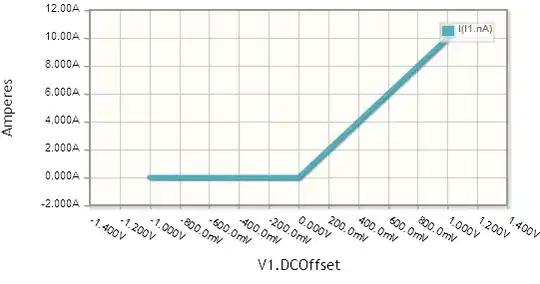
Typically, an I-V characteristic is of a two-terminal device. The plot is of the current through the device against the voltage across the device.
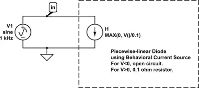
It's standard to model a two-terminal device with ideal circuit elements connected in some way but I think that what's missing from your circuit diagrams are the two terminals that the plotted voltage is measured across and the plotted current is measured through.
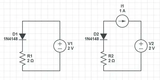
For example, in the left side circuit, if you broke the connection between the diode anode and the positive terminal of the voltage source, and then labelled the diode anode as the positive terminal, you'd have a model for the two-terminal circuit element with the dotted I-V characteristic.
If you then connect an appropriately directed 1A current source in parallel with this model, you get the model for the solid characteristic.