3

I recently started learning electronics on my own due to interest in audio effects because I play guitar so:

I thought I'd start out with distortion pedals, they seemed the simplest to begin with.

The schematic below is from a clone of the famous Boss OD-1 overdrive pedal. I am getting a hold of the thing and starting to understand how it works but I've gotten quite stuck now, I can't find what the function is of a capacitor running into a resistor that goes to ground, as is the case of C3 and R5 here, just can't find it anywhere.

Any help on understanding this is really appreciated.

Greets, Nook
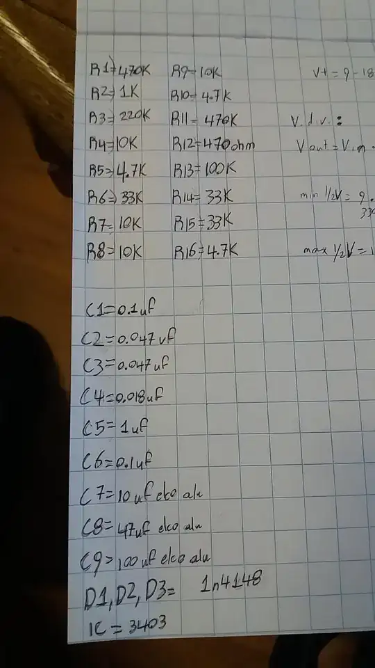
overdrive schematicvalues

Jakub Rakus
  • 2,225
  • 5
  • 18
  • 26
Nook
  • 117
  • 8
  • 1
    I don't even know how to rotate my head to read this schematic. – Eugene Sh. Jan 15 '18 at 14:51
  • 90° counterclockwise, sorry for that, took the picture with my phone on its side.. EDIT: not anymore just changed it to the orientation its suposed to be! – Nook Jan 15 '18 at 14:59
  • I think your drawing gets at least the connection of R4 to ground wrong (It should probably go to 1/2V). C3 R5 forms a highpass network that causes the gain of IC1A to fall to unity at DC, it avoids shifts in the DC conditions when the drive control is altered. – Dan Mills Jan 15 '18 at 16:43

3 Answers3

5

IC1A intentionally is set to have high gain and it's a non-inverting amplifier like this: -

enter image description here

R5 in the OP's circuit is equivalent to R1 above.

However, it has two extra features that work together. The diodes in the OP's circuit heavily clip the guitar signal and this produces "wanted" distortion that can be adjusted by VR1. Note that the signal is clipped asymmetrically to provide a different type of characteristic "sound" compared to symmetrical clipping. The asymmetry means that R5 must then be capacitively connected (via C3) to stop the natural DC offset produced by the asymmetry causing the circuit not to work correctly i.e. it stops the output developing a significant DC offset that would tend to make clipping more or less symmetrical.

Andy aka
  • 434,556
  • 28
  • 351
  • 777
  • A thicko asks: what do you mean here by asymmetrically? To keep the a.c. signal is symmetric around 0V? (This is not me being sarcastic, genuine question.) – DiBosco Jan 15 '18 at 15:10
  • Thanks a lot! I get it now. But does the value of c3 interact with how it stops the developing of this offset? – Nook Jan 15 '18 at 15:13
  • @DiBosco here I mean an asymmetry would clip the positive half cycle of a signal more (or less) than the negative half cycle. This could be about 0 volts if the op-amp had no input offset voltage errors. – Andy aka Jan 15 '18 at 15:13
  • @Nook when you have given enough time for others a chance to answer please consider formally accepting the answer that you feel is most helpful or appropriate. – Andy aka Jan 15 '18 at 15:15
  • Sorry, will take that in account next time, i'm just really excited about understanding this! – Nook Jan 15 '18 at 15:40
1

C3 and R5 are setting the gain of IC1a. At DC the gain is one, and the gain rises with frequency to a max of 1+ (R6+VR1)/R5, as the impedance of the capacitor drops. You can figure out at about what frequency that happens.

George Herold
  • 4,754
  • 1
  • 18
  • 25
  • Ok, so lowering the impedance of the capacitor increases the gain? So i understand according to @andyaka , C3 has to be there to counter the circuit trying to even out the dc offset, but, as you say the impedance has to be low enough for it not to cause a loss in gain? – Nook Jan 15 '18 at 15:36
  • @Nook, The maximum gain is set by the resistor ratio. Changing C3 changes the frequency at which the gain starts to rise above one. (Does that make sense?) – George Herold Jan 16 '18 at 15:47
  • i just noticed that i said impedance of the capacitor, i meant capacitance, sorry for that. Ok,i think i get it now, it has to do with capacitive reactance, right? – Nook Jan 18 '18 at 20:57
  • @Nook, (starting again) Impedance is a fine term for a cap., perhaps better than reactance, which is only the imaginary part. Impedance and it inverse admittance are both complex. – George Herold Jan 19 '18 at 00:22
  • I think i now understand what you mean, from the links suggested in the answer below by @user11599 i understood it should act as a high pass filter, and what you say is it does this adding gain at frequencies above 72,03htz? I think.. i feel like I'm getting closer – Nook Jan 20 '18 at 12:33
0

I'm guessing that the purpose of the C3 R5 is to change the sound by giving the IC1a3403 some characteristics of a high-pass filter. For instance, if you drop the diodes, that stage of the circuit becomes a single-pole non-inverting high-pass filter with the topology shown here.

There is a similar high-pass topology in the 'clipping' stage in the Ibanez Tube Screamer even though the diodes in that design are symmetric. The site Electosmash has done a good stage-by-stage analysis of that stomp box and thinks the purpose of the capacitor/resistor is to modify the sound via high-pass filtering. (the Tube Screamer also has a capacitor in parallel to the diodes, adding a low-pass filter, so that the net result in the Tube Screamer is band-pass filtration. In your circuit, the next stage with IC1d3403 is an active low-pass filter, so you are also imposing a band-pass filter on the clipped signal.)

user11599
  • 171
  • 3
  • Thats a really interesting thought, a week or so ago, when i started with this, i discarted the idea of that being a high pass filter, because until i read your message i thought a high pass filter was a capacitor running into a repeater to ground, with an output taken from inbetween those two, i calculated the cut off frequency with the formula given in the link you shared, and it comes out at around 72.03 htz, which makes a note between D2 and D2b/C2#, this would make sense as a highpass filter, because the lowest note on a guitar (when in standard tuning) is E2 at 82.407 htz, – Nook Jan 20 '18 at 11:58
  • and the low pass filter on IC1D starts cutting off at 884 htz (somehere between A5 and A5#) which also makes sense in most cases, but looking at R12, R13 and C7, that also looks like a high pass filter, but when i calculate the cut off frequency by doing 1÷(2*pi*(R12+R13)*C7 (i couldn't find the correct brackets for the formula, sorry) it turns out a cut off at 1584 htz, now i am certain i am missing something here, because that number makes no sense to me, at 1584 htz it would be filtering out all the low/low-mids of the guitar tone... – Nook Jan 20 '18 at 12:07
  • Resistance* not repeater, sorry, autocorrect... – Nook Jan 20 '18 at 12:08
  • @Nook, I'm guessing that C7 is meant to keep DC out of the output (DC output could damage speakers and won't be of much use musically). Its role is more of a decoupler than it is a filter. There are often capacitors at input and output to keep DC from going to the speakers (output) or pickups (input), along with decoupling capacitors between audio stages. For this purpose the capacitors tend to be relatively large. – user11599 Jan 21 '18 at 07:38
  • Just whent to a online filter cut off calculator and it comes out as 0.2 htz meaning it doesnt cut any important frequencies, so my calculation was wrong haha, it makes sense now, thanks a lot! – Nook Jan 21 '18 at 09:15