1

I lab tested the circuit below, which Olin Lathrop designed in this answer.

The problem is, on OUT (pin 4) of the optocoupler I get 1.7 volts when 240 V is applied to the high voltage (HV) side of the circuit, I'd like the voltage on OUT to be lower (less than 0.8V) to represent a logic 0. How can this be achieved?

The AC current on the HV side of circuit measured 1.1mA.


enter image description here

SamGibson
  • 17,231
  • 5
  • 37
  • 58
Graeme
  • 11
  • 2
  • 2
    Try putting a small capacitor across R3 to see if that fixes the problem. – user57037 Jan 06 '18 at 20:02
  • 1
    Why did you use a DMM to measure 1.7Vdc when the output is a zero-crossing switch (ZCS) pulse at some CTR threshold. If you dont care about ZCS pulses then all you need to do is replace 10k with 1M and add C to choose some time constant for power fail = high. and define the delay time e.g. 400ms = 0.4uF* 1Mohm ( or 0.39uF std value) – Tony Stewart EE75 Jan 06 '18 at 20:45
  • 2
    To remove our guessing: did you measure the 1.7 V with a multimeter or with a 'scope? – TonyM Jan 06 '18 at 21:18
  • a DMM would report his 1.1mA with a half wave in DC mode where as a scope reading one would say 3.3mA peak just as a scope would report the collector going from 3.3V to 0.3V and someone who does not understand how it works is expecting some DC out of an AC current pulse when a storage cap is needed on the output. And then one understands you dont need 10k pullup for a fast rise time but rather 1M for longer decay time. – Tony Stewart EE75 Jan 06 '18 at 22:10
  • Yes, I all measurements were taken with a DMM. – Graeme Jan 07 '18 at 01:11

3 Answers3

6

I assume you measuring it with a voltmeter. The circuit Olin presented provides pulses every half-cycle due to D1. With an oscilloscope you would see that.

If you want to detect the presence of 240VAC at the input, you can either stretch the output pulses with a one-shot (74HC123, 555 or whatever) or perhaps a capacitor from output to ground will do the trick if you're not too concerned about rise and fall times. Maybe try 10uF or 22uF.

Spehro Pefhany
  • 376,485
  • 21
  • 320
  • 842
1

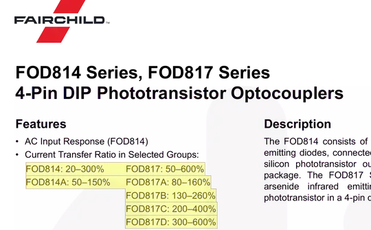
enter image description here

Olin wisely chose the maximum CTR range to improve output saturation but these are also least common and more expensive.

But even if you did not use Olin's "D bin" suffix in the FOD817 then you would have had enough current with 350 Vpk/94kOhm ~ 3.5mA input peak current and a load of 3V/10kohm= 0.3mA will saturate with CTR < 10% (=0.35/3.5mA) as it is called for Optotransistors and from the chart above 20% is the minimum CTR and "D" bin being 300~600%.

Solution?

  • Redefine design to convert AC fail = logic "1" and AC ok = Logic "0" rather than a single ZCS pulse per cycle as Olin intended (for whatever reason)

Replace 10k pullup with 1M pullup and C>=0.39uF

Tony Stewart EE75
  • 1
  • 3
  • 54
  • 182
  • Tony, many thanks for your very considered answer (and indeed to all who contributed). I will lab test the modified cct in the next couple of days and report back. Thanks again. – Graeme Jan 07 '18 at 08:08
  • solution (replace 10k pullup with 1M pullup and C>=0.39uF) worked well, providing a clean logic 0 to Raspberry PI when 240V AC applied. – Graeme Jan 09 '18 at 20:11
  • I trust you understand better now. – Tony Stewart EE75 Jan 10 '18 at 00:00
  • Yes. I studied electronics 30 years ago, but drifted into IT. Now with more time I'm rediscovering electronics and loving it ! Thanks again – Graeme Jan 10 '18 at 19:52
-1

On top of that, make sure the led of the optocoupler gets the specified voltage at all times (usualy between 1.5V and 2V). A very small difference could either make the FET not completely closed if voltage is too low, or damage the led if too high, and possibly resulting in the same effect. 200-240 AC can vary between... well,... 200 and 240V. You should add a very accurate way to supply the led with the right voltage if that's the problem. Resistors are not accurate.

Fredled
  • 1,820
  • 9
  • 17
  • Another reason could be ambiant light. But normaly dim ambiant light should have no or very little effect with a new optocoupler. A damaged optocoupler can become very, very sensitive to ambiant light. – Fredled Jan 06 '18 at 23:20