Skip to end for short-cut solutions
If you used silver coloured conductor wire, there is a good change your experience was naturally poor because the wire was either Aluminum or the component used a welded Stainless steel lead. But items such as leaded resistors are tin plated steel are also silver in color. Pb-free solder requires a slightly higher temperature and is not as easy to flow as obsolete 50/50 tin-lead solder. Make sure it is resin core flux to reduce surface tension and allow easy flow. Then pre-heat the wire at the joint until solder melts on the wire near the tip. You can quickly melt some solder to start the heat transfer then move the solder to the other side and let the heat suck in the solder till it fills the wires. If the gap to the insulation is short an even better solder joint sucks its way under the wire insulation via the wire so that it becomes stiffer and makes a better "strain relief" to the solder joint. This explanation may seem like over-kill for this application, but practice on simple wire joints and understanding of how flux and solder flows towards the heat helps in more difficult joints. It does not take blobs of solder, rather just heat and solder to flow between the strands to envelope the joint all around. If you are soldering to say a Ground pad on a PCB with a ground plane you need a lot more heat and that would be too much for a tiny pad, so awareness of heatsink demand for heat when soldering helps understand how much you need to apply.
In any case, soldering requires a clean tip so there are methods to "tin" your tip or remove dry oxides and the surface needs to be rust free as any oxide is essentially rust. Thus a suitable abrasive such as fine grit for the terminals or even a file to expose the bare metal on a terminal to be soldered will improve "resistance" to liquid solder flow significantly. a.k.a. surface tension.
WHen I started as an EE in aerospace, the NASA trained technicians I worked with and their foreman, the teacher used a soldering manual from NASA that was 4" thick, so there are many levels of skill to be acquired for critical requirements, but when you are done, the wire ought to be able to pass the standard "five pound pull test". If you notice the strands becoming loose or weak around the joint, try again or add a few mm of wire solder to prevent the strands from breaking from twists or pulls. The solder will appear bright and shiny when done and not dull from excessive oxidation ( too long), motion during cooling ( crystals forming ) or too cool ( not allowed to reach full liquidus stage) and thus called a "cold solder joint"
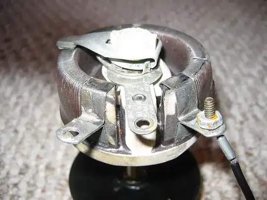
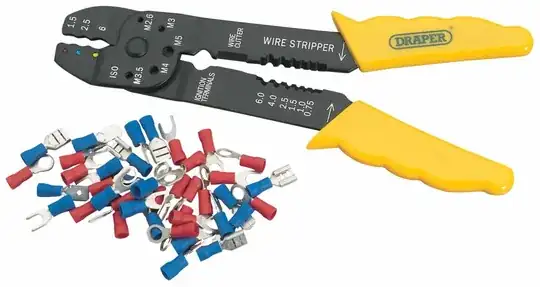
But if you really want to use your existing crimped wire, I think you need a 4-40 x 3/8"L screw ,a 4-40 star washer and 4-40 nut to dig thru the surface oxide that will accumulate. A metric equiv. size will work too. ( My guess is this was your thinking to re-use existing crimped wire, which you may also cut & strip 1/4" = 6~10mm then solder)
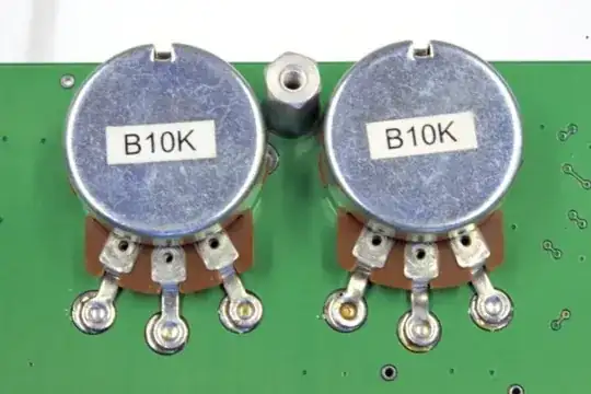
By the way the new pot you have shown will not replace the old one shown as it has signicantly lower wire resistance and higher current (power) handling capability, so make sure the new pot power rating is sufficient and has a similar resistance. (Take it to shop and ask)
Pots come in both Cermet ( ceramic metal) and Wire Wound (WW) for low R, high current types, and also linear and logarithmic sensitivity usually for audio.
HTH's
Tony