Let's consider a theoretical highpass filter:
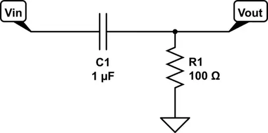
simulate this circuit – Schematic created using CircuitLab
I'm trying to show that the worst-case input and output impedance is R but the whole concept of input / output impedance isn't really clicking for me.
Resistors have impedance. Capacitors have impedance. How can an input or output node have impedance? I think that they must be comparing the node to something but I'm not exactly sure.
Initially I was thinking that input impedance must be the amount of impedance that would be met as the current traveled through my RC filter. If the frequency was high, C1 would look like a short and the current would flow through R1 to ground. If the frequency was low, C1 would look like an open circuit and impedance would be infinite. Having a low input impedance is the worst-case scenario and I just showed that the lowest it could be is R1. So that seems to work.
Following that train of thought, I figured that output impedance must be the amount of impedance that would be met as the current traveled through ..... the rest of my RC filter? This train of thought suggests that C1 is irrelevant because the only place left for the current to go is through R1. That is the right answer but it seems like I got there incorrectly.
Is this right? If not, can you please explain it?
