8

I'm trying to design a 5V UPS. Power to load should switch if line voltage falls below about 4V. Battery voltage may be from 3.8 to 5V. I'm simulating in LTSpiceIV.

I'll be using mosfets to supply battery power to avoid schottky voltage drop. However, the circuit starts to oscillate when line voltage is near 4.4V. Will this be a problem during actual use? Also, how can I replace the other schottky with mosfets? I think the high gain of the op amp in the tl431 may be causing the oscillation, but am not sure. Circuit simulates fine with a schottky instead of the first mosfet after the battery.

I don't have much experience with this. All suggestions will be appreciated.

enter image description here

enter image description here

I added 2 more mosfets and got this. Still oscillates when line voltage is cycled, but seems to simulate ok when I use fixed DV voltages for V1. I wonder if this is a LTSpice quirk, or the timesteps are too small, or if it's a genuine problem.. some race condition which will occur in reality. Power switches to battery when line voltage drops below 4.21V. enter image description here

Indraneel
  • 2,117
  • 1
  • 17
  • 24
  • 4
    You might try to add some hysteresis somewhere. The moment the battery takes over the main supply is no longer loaded and will rise again. Some feed back resistor to the control of U1? (I have not simulated this. Would be willing to, but I am hopeless with LTspice. It would take me an hour to make a circuit like that) – Oldfart Dec 31 '17 at 08:33
  • Which models did you use for the TL431 and AO3401? What does the battery consist of? – Bruce Abbott Dec 31 '17 at 12:50
  • the tl431 model came from a huge bunch of models I downloaded from the net. It has mostly worked well so far. The AO3401 came from the manufacturer site http://www.aosmd.com/products/mosfets/p-channel/AO3401 The battery is V2 in the schematic. I'm keeping my options open on that (could be lithium or 3xAA NiMH, or 4V lead acid, or 3xAA alkaline, or a 5V lithium battery pack). I will be using a DS1307 in my load circuit, and it will be battery backed up at 3V, so the load will need at least 3.75V to be able to read the clock chip. – Indraneel Dec 31 '17 at 13:21
  • 2
    No offense but your schematic is too hideous to look at. There is a single chip solution for this from Texas Instruments for ORing through NFETs. http://www.ti.com/lit/ds/symlink/lm74610-q1.pdf – lucky bot Apr 14 '18 at 21:44
  • 1
    That is the most compact schematic I've ever seen – Voltage Spike May 02 '18 at 21:12
  • There's only so much screen space, and all the components compete for it! See the one at the bottom with my answer, with fewer components. – Indraneel May 03 '18 at 11:31
  • Try Ctrl- to zoom out. then parts should get smaller so you can add more parts. Did you fix your design error yet? – Tony Stewart EE75 May 05 '18 at 11:14
  • If the parts are too small, I can't see them properly and quickly anymore! I fixed the design errors, got rid of the TL431. My answer is already posted at the bottom. – Indraneel May 05 '18 at 11:27
  • Do you think you could mark the most suitable answer as accepted? It might be your own. – pipe May 08 '18 at 06:13
  • 1
    @pipe, I think he deserves the bounty, it's the only working solution here. I wanted to point to his solution in my answer but I couldn't make a simulation to check-it. It had my vote. – Dorian May 08 '18 at 10:21
  • @Dorian Done. :) But I would also like to see the little green checkmarks, makes for better site statistics. – pipe May 08 '18 at 10:56
  • 1
    You guys put me in a moral dilemma, so I came up with a better answer, and it also looks non-hideous. I'm an electronics noob, so could not precisely figure out what is causing the oscillations, but it has something to do with how close the gate and source voltages become, when mains takes over. Hope you guys don't mind my accepting my own answer. – Indraneel May 08 '18 at 12:00
  • 1
    You're welcome, to more updates below. – Indraneel May 08 '18 at 13:13

3 Answers3

3

TL431 is working out of the specifications, the datasheet states a minimum 0.7mA to 1mA cathode current required for the reference to work properly, see the tables listed from page 5 to 13 "minimum cathode current for regulation" parameter.

At a first sight R1 is way to high even before the voltage will be cut by U3. Also the cathode voltage must be at least close to the reference voltage, see the comparator example in page 21 and the table in page 22 and also your common sense on how a reference should work.

Maybe lowering the value of R1 and feeding it from the highest voltage source through two diodes might do the job.

schematic

simulate this circuit – Schematic created using CircuitLab

If your circuit works well on battery and you're worried about the higher current consumption then you could make a compromise and slightly modify the schematic to supply TL431 in parameters only when V1 is higher enough.

schematic

simulate this circuit

Update

I couldn't make your circuit work as is or with slight changes.

The voltage drop detector doesn't work as intended since M1 transistor is always open when U1 gets in the working range with cathode voltage higher than 2V.

Dorian
  • 2,546
  • 2
  • 11
  • 20
2

The problem is a linear gain feedback loop will amplify noise and oscillate from insufficent phase margin in the closed loop without an integrator like unity gain stable Op Amps. Speaking of Op. Amps., the TL431 is a programmable Zener with low gain that may behave like a low gain closed-loop Op Amp with a low gain of (R6+R2)/R2 * 2V = 4.94V.

Datasheet violation

(Kudos to Dorian for this fault detection). This answer is more towards how to design any solution with example of OR FET switch and statement on Specs 1st, choice 2nd (make or buy) then 3rd make if you think you can do better or just want to learn by errors in step 1.

Minimum cathode current for I min See Figure 20 Vka = Vref 0.4mA min 0.7 mA typ regulation
The value and location of R1 is wrong. It is impossible for U1 to reach 5V out from Vbat =4V pullup on R1 thus only leakage current. wrong.

Always compare at some threshold that is less than the voltage you are trying to regulate, NOT MORE.

You want to sense 5V dropping below 4V then switch outputs.

Unfortunately the 4V is not a good source for USB so rethinking your requirements is necessary and change design parameters.

  • Perhaps you want to enable 4V bat to boost to 5V when USB drops.
  • Perhaps you want 5V "UPS" to operate from Vbvat down to Vmin so a boost regulator is needed
  • Perhaps you also want to regulate charge to Vbat

    • These are always defined in your overall system design spec 1st "a priori" with a list of variables and min-max values just like any datasheet

    enter image description here

Suggestion for all Newbies:

Start over with proper design specs for all conditions of Input and output.

Tony Stewart EE75
  • 1
  • 3
  • 54
  • 182
1

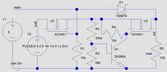
Oh well, a bounty! I finally went with this non hideous looking circuit that still oscillates at battery voltage, but stable at above battery voltage! Battery voltage is likely to be max 4.5V with lead acid, which is the lower limit of the USB spec.
enter image description here

The trouble is not the mains voltage which may not be stable. It may be unstable for just an instant and is not an issue. If it is really unstable or out of spec, replace the wall wart. There may be many things wrong with a wall wart that cannot maintain voltage. Would not want to trust it to power microcontrollers.

The real problem is the battery voltage which needs to be cut off once it falls too low to avoid permanently damaging the battery. Adjust resistors to taste. Circuit is less expensive than before, and more reliable. Schottky is my friend, I don't mind him anymore! He saved me a lot of headache. The circuit running from battery needs to be able to operate at far lower than 4.7V anyway.

PS: I don't like single chip solutions, they play hard to get on my side of the planet. Besides, I can't smoke them willy nilly...

UPDATE:

Here's a much more elegant (non hideous) looking schematic. As Dorian and others have pointed out, the TL431 requires a minimum current to operate. So then, it requires a reliable voltage source to operate. Which means, it has to operate from the battery. The TL431 really has to act as a comparator, otherwise the mosfets will be in linear mode and will start to heat up. The gate voltage becomes very close to source voltage of U2 due to mains voltage coming in. This is the actual cause of the oscillations above, not the datasheet violation of the tl431. The oscillations will happen even if the tl431 is removed completely. The mosfets being logic level does not help either. For the circuit below, the mosfets have been replaced with N channel mosfets. However, this causes a voltage drop at source when fully on. Voltage to load varies from 2.8V to 4.7V and the circuit works perfectly without oscillations. It may be possible to switch position of R6 and the tl431, but then the tl431 anode will only go up to 2.5V, and the mosfets (now replaced again with P channel mosfets) will always remain on.
enter image description here

But then, since the tl431 is being used as a comparator anyway, and also requires a supply current to work, why not replace it altogether with a lower current comparator like device.... Unfortunately, lm358 does not reach the +ve rail, and the mosfets are logic level. So when the mains voltage is high, a reverse current flows into the battery (0-60mA when battery drops from 3.85 to 3.6V). This will trickle charge the battery when charge goes low. That may hopefully be a good thing. Circuit works perfectly at all mains voltages from 2V to 5V, with no oscillation. Circuit does depend on the voltage drop across the diode. Replacing it with 1N4148 will not guarantee it's working without oscillations if battery voltage is high. Circuit did not simulate correctly with the LM393 which is an actual comparator. Proper testing is suggested before use.
enter image description here

Oscillations are caused by some kind of race conditions at the source and gate voltages of the second mosfet. I still don't know exactly what is going on. But the modified circuits work, and solves my problems. This is not the perfect answer. But it is the best answer. I am accepting my own answer.

more update!

Tweaked again, look closely, mosfets are flipped on the Y axis so source is inside. Circuit is now fully stable at all mains and battery voltages. Depending on the mains to battery voltage difference some trickle current may flow to the battery (maybe 60mA) in some cases. Circuit works with either a schottky or a 1n4148 (although obviously with 1n4148 it will draw from battery more if battery voltage is high). Works with real comparator LM393 as well as LM358, with no changes. Opamp/comparator accepts mains or output voltage at non inverting pin for comparison with battery. I think it's close to perfect. Thanks for the bounty!
enter image description here

PS: probably should replace 1N4148 with 1N4007, but 1N5819 is best.
Indraneel
  • 2,117
  • 1
  • 17
  • 24