You can probably tell by my comments that it is not clear to me what you are trying to do. But I just noticed that I failed to correctly read something you wrote:
I was wondering if there is any way to design/size a "single"
transistor or MOSFET component?
Since you show a picture of a BJT, mention the word "transistor" (which can mean quite a range of things including BJTs and MOSFETs), and then included "MOSFET", as well, I was left thinking that you were pretty deep into fairly technical aspects of transistor design and wanted to know if LTSpice could support your interests.
So I commented in light of that interpretation.
But it is possible to read things differently, looking with fresh eyes at this. And perhaps Mike directed you correctly in his comment.
For MOSFETs in LTSpice, you can use the nmos4 symbol and place it on the schematic. If you right-click on that symbol, you will see a dialog box that looks like:
And I think you can see where you can specify various details for the MOSFET. You can do this differently for each and every one you put on the schematic, so there is no requirement at all that they be the same.
Another approach is to drop down a regular schematic symbol (BJT or MOSFET) and then right-click on the Value (for example, the "NPN" that shows when you first add an NPN BJT to the schematic.) To begin, you will see something like the following if you do it correctly:
Here, change it to some special model name you want to create. Like "MYNPN" for example.
You can also control-right-click on the symbol and you will see, under "Value", a designation there that you can now edit. If you choose this method, the display will look something like:
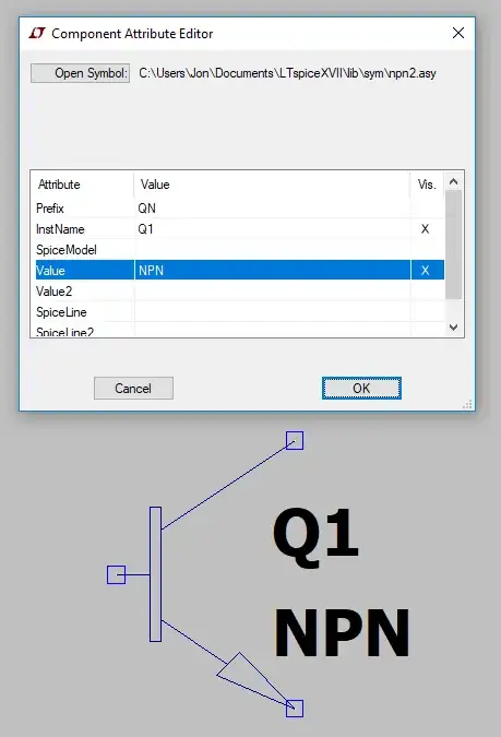
Either approach works. The main thing is to change this name to something that isn't found anywhere else. Make up a name.
Once you have a named part, like this, you can now add a "card" on your schematic. You do this by hitting the "S" key. A dialog pops up looking like this:
Note that I've added some text. This text tells Spice that I want to define a new "model" of a device. I provide the name for it (MYNPN) and then use "ako:" to tell Spice to grab up a default model that I'd like to modify. In this case I used "2N2222" which happens to be in the standard BJT library. Then I specify the NPN() part at the end. Here, I can insert any specific parameters I'd like to over-ride in my own special model. The other parameters, those that I don't over-ride, will remain the same as in the default model I mentioned already.
Now, you have a new model on the schematic and LTSpice will demand that you place this new "card" on the schematic somewhere. Stick it in any convenient place. Location doesn't matter.
You can always right-click on these "cards" to change them, too. So you aren't stuck with mistakes you might make.
You could also NOT use the "ako:" keyword and instead just fill out the entire NPN() part of the "card." It is your call how you want to do that. If you use "ako:" then you get to pull up a bunch of default values that are similar to where you are headed and only modify the parameters you want to modify. If you don't use that keyword, then there still are defaults but now these are hard-coded ones deep inside of LTSpice and listed in the help file on the BJT. Either way, you over-ride the parameters you want to over-ride.
In short, you can create unique variations.
You can also parameterize them and make LTSpice go through a range of values. For example, you can tell LTSpice that you want the \$\beta\$ of a transistor to be varied from 100 to 300. You do this by setting up a new parameter value and using it within your .model card.
For example,
That shows two cards. One for the model, which refers to the parameter name BETA as an expression rather than a hard-coded value. Then I added a .step card which causes the parameter value to be modified repeatedly, starting at 100 and going to 300 in steps of 20.
There is a lot more you can do with LTSpice.
I very strongly recommend the following book:
The Spice Book
Andrei Vladimirescu
Definitely get yourself a copy of it. You won't be sorry.