3

I've been trying to figure out what looks like a clipping issue in the linked circuit.

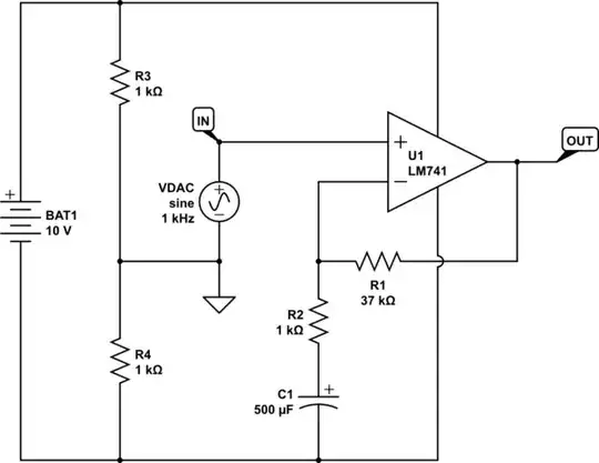
Our input is a 8 kHz 120 mV sine voltage signal coming from an AD9850. We are trying to amplify it to a 5V signal. The signal is clipping at 1.3 Vpp well below our rails of +/-5V.

We've upped the supply to 20V (+/-10V) but the "clipping" remains (the clipped signal peak to peak slightly increases to approximately 1.8V). We have a slightly uneven splitting for the supply voltage on the op amp at 5.5V and -4.5V, but from what I read that should not be causing that much of an issue. We were having the exact same problem with a OPA2134PA. The problem persists up to +/-30V and adding parallel resistors to the virtual ground capacitors did not help, either.

The negative peak is clipped less than the positive peak. We are pretty sure our capacitors are oriented correctly (we have \$C_1\$+ facing the positive side of the supply, \$C_2\$+ facing the ground and \$C_3\$+ facing the AC input).

schematic

simulate this circuit – Schematic created using CircuitLab

Null
  • 7,448
  • 17
  • 36
  • 48
Paul
  • 63
  • 6
  • 2
    That is not a virtual ground. You need to add two resistors in parallel with C1 and C2. – Trevor_G Dec 27 '17 at 15:28
  • 9
    We need a "Go stand in the corner.." button to click every time someone uses a 741.... – Trevor_G Dec 27 '17 at 15:34
  • 1
    In that corner there should also be a huge stack with copies of Opamps for everyone: http://web.mit.edu/6.101/www/reference/op_amps_everyone.pdf for everyone to read and take home after reading. – Bimpelrekkie Dec 27 '17 at 16:19
  • 1
    And read Andy aka's answer to this question: https://electronics.stackexchange.com/questions/304521/reasons-not-to-use-a-741-op-amp for a list of reasons **not** to use a 741 while standing in the corner. – Bimpelrekkie Dec 27 '17 at 16:25
  • But the datasheet specifies Recommended Operating Conditions where the supply is given as nominally +/- 15V. – Finbarr Dec 27 '17 at 16:35
  • We figured we should stay away from the max recommended it says nominal is from 5->15 on the data sheet but we'll try. – Paul Dec 27 '17 at 16:39
  • 1
    What you need to stay away from are the **maximum ratings** which is +/- 18 V (or more depending manufacturer) for a 741. So even at +/- 15 V there's some safety margin. – Bimpelrekkie Dec 27 '17 at 16:54
  • Even at the recommended \$ \pm 15V \$ supply, the 741 might clip at \$ \pm 12V \$. Hence, use a proper \$ \pm 15V \$ split rail supply if possible or a single \$ 30V \$ supply with a buffered virtual ground at \$ 15V \$. – altai Dec 27 '17 at 16:58
  • Indeed, provide a proper +/- 15 V supply and **measure** that it is +/- 15 V. Disconnect the input sinewave, is the opamp's output close to 0 V? If so connect signal only apply a few mV, signal OK ? Then increase until it clips. – Bimpelrekkie Dec 27 '17 at 17:01
  • Tried +-15V only getting 2.8V signal with a little bit of clipping. Should I increase the feedback resistance? – Paul Dec 27 '17 at 17:05
  • 5
    741 problems can usually be solved by carefully removing the 741 from the breadboard and placing it in a suitable rubbish bin, and replacing it with a decent op amp of more recent design than *the late 1960s*. – Ian Bland Dec 27 '17 at 17:18
  • 1
    Lol any recommendations for some good general purpose modern opamps. TBH only reason I went for a 741 was because that's the cookie cutter amp that is taught throughout college. – Paul Dec 27 '17 at 17:36
  • Opamp recommendations are difficult, there are so many. Knowing what you need out of the amp, then a parametric search are usually the way to go. Off the top of my head: pin-compatible, common and cheap, you might take a look at the TL0xx type chips from TI: www.ti.com/lit/ds/symlink/tl031.pdf or www.ti.com/lit/ds/symlink/tl081a.pdf – evildemonic Dec 27 '17 at 18:05

3 Answers3

2

The big problem with the schematic as drawn is that your zero-volt reference is free to float anywhere between either supply rail. Try adding low-ish value resistors << 1k, if possible, across C1 and C2. This will hold the ground reference voltage a bit better.

If that improves things then consider either a split rail supply or replacing the lower resistor with a 5 V Zener diode to hold the zero-volt line at +5 V relative to the negative supply.

schematic

simulate this circuit – Schematic created using CircuitLab

Figure 1. Resistive and Zener ground generation.

Transistor
  • 168,990
  • 12
  • 186
  • 385
  • Or, and I hate to say it.. add another 741 to buffer the virtual ground. – Trevor_G Dec 27 '17 at 15:32
  • 2
    I'm afraid we think too much alike. We could take alternating shifts on the site or arrange holiday cover for each other. I'll be in touch! – Transistor Dec 27 '17 at 15:36
  • LOL.. no doubt ;) – Trevor_G Dec 27 '17 at 15:37
  • Hey guys we added the resistors in parallel to the capacitors and our output is still clipping starting at around 1.1V when we put a 10k resistor on the feedback. We are grounding everything but the AC input on the virtual ground. Should we be separating the OPAMP +IN ground from the virtual ground? (No zener diode on hand to see if that configuration would fix it) – Paul Dec 27 '17 at 16:21
  • 1
    @Paul maybe you have used 10x scope probes and didn't realize. – Andy aka Feb 14 '18 at 14:07
0

The AD9850 circuit has (supplied with positive voltage) a DC offset voltage at the output, and the 500 uF capacitor used for coupling the signal to the amplifier probably also has a low leakage resistance, hence the DC offset and the different behavior on the positive and negative side.

JRE
  • 67,678
  • 8
  • 104
  • 179
Antonio51
  • 11,004
  • 1
  • 7
  • 20
0

On page 2 of the AD9850 datasheet it states that its output impedance is typically 120kΩ.

I find that hard to believe, but that's what it says. It just doesn't sound right, for a 125MHz device. Even 1pF at the output would cause heavy attentuation at 1MHz. I think that must be a typo.

Anyway, even if they are an order of magnitude out, it doesn't stand a chance driving your 1kΩ input impedance amplifier.

I'd buffer that DAC output with a voltage follower, prior to any gain stage. Or perhaps you could employ the opamp in a non-inverting configuration, with high input impedance:

schematic

simulate this circuit – Schematic created using CircuitLab

Simon Fitch
  • 27,759
  • 2
  • 16
  • 87