1

I want to drive LEDs using an Arduino Due and a MOSFET. Below is the circuit I am using, taken from another post: Driving LED strip from microcontroller

circuit schematic

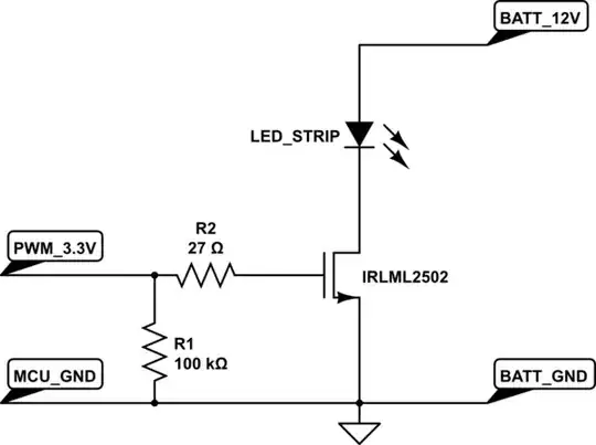
I replaced the transistor in the picture with a IRLB8721PbF. Datasheet:https://cdn-shop.adafruit.com/datasheets/irlb8721pbf.pdf

The LED_STRIP is replaced with two LH351B white LEDs connected in series. Datasheet:http://www.samsung.com/global/business/business-images/led/file/product/lighting/201504/Data_Sheet_LH351B_Rev.4.3d.pdf

The forward voltage of the LH351B is approximately 3V, so I am using 6V as my power supply. Basically I want to keep turning the LEDs on and off. I noticed that when I increased the switching frequency, for example 100kHZ, the LEDs were dimmer than what it was when switching at a slower frequency like 1kHz. What could be causing the decrease in brightness?

I believe LED should be able to switch at the nano seconds range? And the MOSFET I am using has rise/fall time at nano seconds as well. Does it have to do with the microcontroller? Below is the code I am using, just a simple digitalWrite using port manipulation:

    PIOD->PIO_SODR = 1<<8; //HIGH on pin 12
    //digitalWrite(12, HIGH);
    delayMicroseconds(10);


    PIOD->PIO_CODR = 1<<8; //LOW on pin 12
    //digitalWrite(12,LOW);
    delayMicroseconds(10);
    }

--EDITED--

full code:

    #include <SPI.h>
    #include <SD.h>
    File dataFile;

    void setup() {
      pinMode(12, OUTPUT);
      Serial.begin(210000);

      if (!SD.begin(10)) {
        Serial.println("Card failed, or not present");
        return;
      }
      Serial.println("card initialized.");
    }

    void loop() {
      int myData_read;
      dataFile = SD.open("DATALOG.dat");
      myData_read = dataFile.read();
      //Serial.println(myData_read);
      for(int i=0; i < 8; i++){
         if((myData_read & (1<<i)) >> i){

            PIOD->PIO_SODR = 1<<8; //HIGH on pin 12
            //digitalWrite(12, HIGH);

            delayMicroseconds(5);
          } else {

            PIOD->PIO_CODR = 1<<8; //LOW on pin 12
            //digitalWrite(12,LOW);
            delayMicroseconds(5);
            }
      }
    dataFile.close();
    } 
Wei T
  • 13
  • 5
  • 1
    whats the max drive of an Arduino pin? – Trevor_G Dec 23 '17 at 01:21
  • @Trevor I found some information here https://www.arduino.cc/en/Hacking/PinMappingSAM3X. I think its 15mA and 3.3V for the pin I am using – Wei T Dec 23 '17 at 01:32
  • 2
    That's pretty small to drive a mosfet gate capacitance – Trevor_G Dec 23 '17 at 01:38
  • 2
    Your IRLML2502 FET has a Gate-to-Source capacitance of 740 pF (typical), from its datasheet. I haven't the energy at this time of night to look up the I/O pin current and work out how quickly it can charge/discharge this capacitance through a 27R resistor and therefore how slow your edges are. (Personal guess: not very slow, doubt they're the cause but you can work it out by looking up the current and transposing Q = CV = it.) Also, how's your wiring for carrying 100 kHz, is it three foot long of spindly wire? And can your LED average a current? Stick 10 uF across the LED, see if it changes. – TonyM Dec 23 '17 at 01:46
  • 3
    No way an LED can switch at nano seconds... for the same reason a standard diode can not do it... most LEDs start topping out around a few kHz or 10s of kHz. Higher speed capable ones will have specs on junction capacitance etc that can help you estimate the peak switching frequencies. – MadHatter Dec 23 '17 at 02:55
  • @TonyM I see, I will take a look at the calculation. The wires are all less than 5cm. I put a 10uF across the LED but no change in brightness is observed. – Wei T Dec 23 '17 at 03:14
  • https://electronics.stackexchange.com/questions/79373/how-to-choose-right-pwm-frequency-for-led – Mitu Raj Dec 23 '17 at 03:19
  • 2
    How about taking scope traces of the transistor drain, instead of speculating about code or drive strength/capacitance? What model of an oscilloscope you are using during code debug? – Ale..chenski Dec 23 '17 at 05:10
  • Obvious idea, @AliChen, but you're speculating that the OP has access to a 'scope. Sounds like a home project to me, as I speculate... – TonyM Dec 23 '17 at 08:53
  • 2
    @TonyM, my extensive experience of dealing with developers of firmware indicates that anyone developing any interface with hardware and not using a scope is wasting everyone's time. A two-channel PC scope (+logic analyzer) is not a big expense nowadays, but it will save **a lot** of time and nerves. – Ale..chenski Dec 23 '17 at 17:52
  • @AliChen, oh I know that a scope's useful, not the must-do-else-"wasting everybody's time" bit though - sounds like my extensive experience is different to yours :-) But it's the wrong starting point if the OP hasn't access to that gear. Some are school age, in a bedroom with a few boards, trying to explore and learn. No 'scopes there, I'm afraid. What is there is enthusiasm and interest to be encouraged and helped. Which, of course, is the solitary objective of this site. And a place for us to learn too, regardless of our "extensive experience" :-) On that note, a very Merry Christmas to you – TonyM Dec 24 '17 at 22:29
  • 1
    @TonyM, Merry X-mas to you too. Although in this country all public was instructed by government-inspired policies to say "happy holidays", otherwise you might offend some clusterfck. Oh, my. – Ale..chenski Dec 24 '17 at 23:26

2 Answers2

3

You haven't shown us enough of your code, but presumably this fragment is embedded in a loop of some sort, perhaps even an Arduino-specific loop() function.

What this means is that your "off" time is not equal to your "on" time. The "on" time is simply the 10 µs delay, but the "off" time is the 10 µs delay plus the loop overhead — which might include the overhead of exiting the loop() function and then re-entering again.

As you decrease the nominal delay value, that loop overhead becomes a greater fraction of the total period, skewing the duty cycle and therefore the LED brightness.

This will be obvious if you simply look at the output pin with an oscilloscope.


Looking at the "full code" in your edit, there are many ways it could be optimized. I would try something like this:

#include <SPI.h>
#include <SD.h>
File dataFile;
int myData_read;

void setup() {
  pinMode(12, OUTPUT);
  Serial.begin(210000);

  if (!SD.begin(10)) {
    Serial.println("Card failed, or not present");
    return;
  }
  Serial.println("card initialized.");
  dataFile = SD.open("DATALOG.dat");
  myData_read = dataFile.read();
  //Serial.println(myData_read);
  dataFile.close();
}

void loop() {
  for (int i=0; i < 8; i++) {
    if (myData_read & (1<<i)) {
      PIOD->PIO_SODR = 1<<8; //HIGH on pin 12
      //digitalWrite(12, HIGH);
    } else {
      PIOD->PIO_CODR = 1<<8; //LOW on pin 12
      //digitalWrite(12,LOW);
    }
    delayMicroseconds(5);
  }
}

There's no reason to read the file over and over again in the loop, and the>> i in theif statement is completely superfluous.

Dave Tweed
  • 168,369
  • 17
  • 228
  • 393
  • Or, otherwise, try putting the code snippet from the question in a for(;;){} block and see if the behavior is different? – vicatcu Dec 23 '17 at 02:03
  • @Dave Tweed♦ I think you pointed out a serious flaw in my design. The full code (edited above) involves reading a stored binary data on a SD card, and toggle the LED to send 1(on) and 0(off). Every line of code takes some time to execute, causes more difference in the "on" and "off" time. Any suggestion on how to improve the code? (Perhaps I should ask this in a separate post) – Wei T Dec 23 '17 at 02:58
  • @vicatcu Yes the behavior is different! The LEDs are bright again. Avoid going into the loop() function solves the unequal LED on/off time. – Wei T Dec 23 '17 at 03:01
  • 1
    If you need really precise timing, you should drive the LED directly from one of the hardware timers. This will also entail the use of interrupts to make sure that the software updates the timer settings as soon as possible when required. – Dave Tweed Dec 23 '17 at 03:07
0

LED cannot be toggled at such high frequency. It will not get enough voltage in that time interval to fully turn on and hence it remains dim or even off.

Mitu Raj
  • 10,843
  • 6
  • 23
  • 46
  • Is there a way to calculate the maximum frequency a LED can toggle? Also any suggestion on how to effectively transmit data using blinking LEDs? – Wei T Dec 23 '17 at 01:36
  • 4
    This is simply incorrect. LEDs are not slow devices. – Dave Tweed Dec 23 '17 at 01:43
  • 1
    Real world -- How about switching time due to series resistor, combined with junction capacitances of diode ? Check -> https://www.google.co.in/url?sa=t&source=web&rct=j&url=http://web.iitd.ac.in/~shouri/eel201/tuts/diode_switch.pdf&ved=0ahUKEwilisqDi5_YAhXKs48KHcF-DmcQFggkMAA&usg=AOvVaw1LhkYVBqknM7AD1SCBoDa9 – Mitu Raj Dec 23 '17 at 02:34
  • 1
    Give a square wave input to a Resistor - LED Circuit and gradually increase the input frequency and observe the changes. – Mitu Raj Dec 23 '17 at 03:09
  • 1
    Already discussed and accepted here ---> https://electronics.stackexchange.com/questions/79373/how-to-choose-right-pwm-frequency-for-led – Mitu Raj Dec 23 '17 at 03:19
  • 1
    @MITURAJ Thanks, it gave me some idea on how to improve the current design – Wei T Dec 23 '17 at 03:32