46

I'm wondering why an antenna has a board trace that follows a certain "squiggly" shape. This doesn't have to apply to only antennas; I'm sure that there are other components that have changing paths for various reasons, but the antenna usually retains this shape.

You can see it on the right in this picture. What is the significance behind a trace like this?

example antenna

(source)

This question might be related to electromagnetics, but I think the answer should be simple enough.

EDIT: I should clarify that I'm looking for explanations dealing with radiation and impedance. Also, any comments on why a design like this would not be efficient for a high-frequency system would help.

stevenvh
  • 145,145
  • 21
  • 455
  • 667
Ci3
  • 805
  • 1
  • 9
  • 13
  • 12
    Can't we talk about something else? I hated antennas in college. – Federico Russo Jun 27 '12 at 10:27
  • Did you get it from [this web page](http://www.penguin.cz/~utx/hardware/Bluetooth_receiver_Enjoy_BT-AU01/)? – starblue Jun 28 '12 at 07:46
  • 3
    It's called a "meander" antenna. [Here](http://www.st.com/internet/com/TECHNICAL_RESOURCES/TECHNICAL_LITERATURE/APPLICATION_NOTE/DM00024648.pdf) is a good description of it. – Leon Heller Jun 27 '12 at 10:11

3 Answers3

21

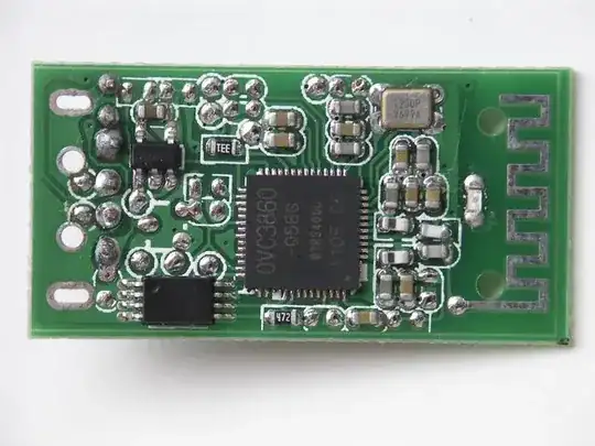
This is referred to as a meander antenna, which is a specific type of folded dipole.

Advantages:

  • Improve omnidirectionality
  • Smaller space requirements

Disadvantages:

  • Tuning becomes more critical
  • Losses are higher than a standard dipole

The Freescale App note, "Compact Integrated Antennas" gives a brief overview of several options, included the meander, for on-PCB antennas. It doesn't give specific design parameters.

A 1982 dissertation, "Meander Antennas" provides some guidance on the mathematical models used to understand and design meander antennas, but goes rather deeper than most EEs will want to venture for simply designing an antenna.

The reality today is that most PCB antenna design of this type is usually done with the aid of an antenna design CAD package. The antenna performance depends on not just the physical layout, but also the materials used, and the shape of those materials, for the PCB substrate, copper, and mask. The software still has some limitations, and so extensive testing is done to validate and tweak the design once it's fabricated. An example of free antenna analysis software is 4nec2 which can evaluate many types of antennas.

When designing a meander antenna, start with a trace the length of the ideal dipole, fold it into the desired shape and space, then perform numerical analysis to determine the radiation pattern and efficiency. Some CAD software has wizards that can help you choose an optimal pattern for a given space, but I have not yet seen a book or guide that gives optimal pattern information that can be applied generally to meander antennas.

mng
  • 1,330
  • 8
  • 9
Adam Davis
  • 20,339
  • 7
  • 59
  • 95
  • It's nothing to do with a folded dipole!!!! – Leon Heller Jun 28 '12 at 15:40
  • 2
    @LeonHeller There are many types of folded dipoles. This is one of them. Many ham radio enthusiasts think of a specific type of antenna when they say "folded dipole" but in the field of antenna design "folded dipole" is a descriptive term, not a specific antenna design. The meander antenna is a form of folded dipole, where there are many folds. If you have a different classification for the meander antenna then please submit an answer that includes the basic antenna design this evolves from if it's not a folded dipole design. – Adam Davis Jun 28 '12 at 15:52
  • It isn't a dipole. – Leon Heller Jun 28 '12 at 16:13
  • @LeonHeller I disagree here, this is an attempt at taking advantage of the dipole, more specifically the monopole which em guys often just say dipole because that is what you are trying for with an image normally. This is something they attempted after a folded dipole by what I read online. This is a more extreme version of a the Inverted-F antenna. – Kortuk Jun 29 '12 at 13:36
  • @AdamDavis If you bring over some of the design methods to your post for it I will reward you with a bounty, would 100 be enough of a bribe? – Kortuk Jun 29 '12 at 14:46
  • 2
    I agree with Leon, the [dipole](http://www.antenna-theory.com/antennas/dipole.php) reference is distracting and confusing. As a dipole is normally a balanced antenna, with the most basic being a [half-wave dipole](http://www.antenna-theory.com/antennas/halfwave.php) as an efficient and effective RF radiator. I assume Adam means either half or quarter wavelength, which then makes sense. I have never seen reference to an antenna with multiple acute angles called a folded dipole, it does appear to be non-standard usage. – mctylr Jul 05 '12 at 01:06
  • Update on the link in the post which is not working anymore. https://www.nxp.com/docs/en/application-note/AN2731.pdf – Lyoner Jun 08 '22 at 12:55
11

An antenna needs to have a certain length to work well at a given wavelength, which is determined by the frequency.

Though it is far from as simple as that, the exact shape and surroundings also play a role, as they influence the electric and magnetic fields the antenna should emit.

Unless you want to study antenna design you can think of it as black magic.

Edit: I think the meandering shape it mostly to get a longer antenna into this small space.

The OVC3860 chip is for Bluetooth audio, so it runs in the 2.4GHz band, with a wavelength of about 125mm. From the 0.4mm pitch of the OVC3860 I estimate the length of the antenna trace as 34mm, which is about 1/4 of the wavelength (actually somewhat more, because the signal will propagate at a speed slower than the speed of light in the trace). This is a fairly normal length for a single-ended antenna.

starblue
  • 6,462
  • 2
  • 21
  • 35
  • 5
    If I did want to study antenna design could you expand upon why that shape is necessary? – Ci3 Jun 27 '12 at 08:08
  • I think the meandering shape it mostly to get a longer antenna into this small space. But the exact shape is as much black magic to me as to you. – starblue Jun 27 '12 at 09:32
  • I'm not so sure about that. Yes, it does need to be a certain length; however, there are older antenna configurations that have a variety of shapes. – Ci3 Jun 27 '12 at 09:39
  • In case you want to simulate it: http://dougneubauer.com/fdtd/ – starblue Jun 27 '12 at 11:55
  • 8
    I think it's amusing that this answer, which basically boils down to "I don't know" with respect to the OPs question, gets 5 upvotes :) – vicatcu Jun 27 '12 at 14:19
  • @ChrisHarris it is because they are trying to fit one of the best antennas into a small place, a half wavelength dipole(monopole here). There are many ways to make antennas and this is just another attempt at a low cost efficiency method. I am trying to decide between giving a bounty to one of the EM members that is lower in rep or writing a full answer myself, if no answer shows up in a day or two that is thorough I will pick one and take action. I have found some good resources for this design online. – Kortuk Jun 28 '12 at 03:23
  • @Kortuk: That sounds good! I'm only beginner in EM, but I would like to see a more in depth explanation relating to EM. – Ci3 Jun 28 '12 at 03:36
  • @starblue FDTD would be one of my last choices for modelling an antenna, but it is probably the "easiest" numerical method, very much is not the best though. – Kortuk Jun 28 '12 at 13:00
7

Pure guesswork here, as I'm no EM guy, but:

  • The length of the antenna will be dependent on the wave-length of the signal being sent.
  • As a result of the termination (open at one end) of the antenna, there will be reflected waves coming back down the line and this will result in interference.
  • If designed to do so, this interference would result in a standing wave phenomenon along the line.

Now, this is where I think that the squiggly shape has to do with helping to amplify the EM waves sent through superposition of the waves at calculated fixed points along the line. Possibly at the peak of the standing waves.

sybreon
  • 1,591
  • 1
  • 12
  • 13