8

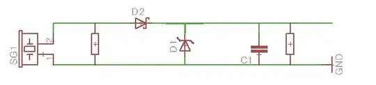
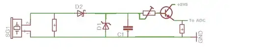
I am completely new to electronics, and am trying to learn by building an electronic drum set. I've found lots of examples online of circuits to condition the output from a piezo to be read by a controller (a Netduino in my case). The circuit I'm using looks something like this.

  1. A Piezo (connected from the drum to my breadboard w/ some cat5 cable)
  2. A 470k resistor in parallel
  3. A Schottky diode in series (on the + line)
  4. A Zener diode in series (3.3v on the + line)
  5. A 1M resistor in parallel
  6. A 0.1uF capacitor in parallel
  7. A Netduino analog pin (and the ground line connected to the Netduino ground pin)

I currently have 6 of these circuits attaching to the 6 analog pins on my Netduino. The circuit is doing a great job of both not missing any hits on the drums as well as giving a pretty good dynamic range of velocity/volume readings. The problem is that when I strike any of the drums very hard, I'm getting some nasty crosstalk (i.e. I hit one drum, but multiple drums are signalled). I've been stuck on this for a few weeks now and have tried tweaking the circuit in every way I can think of, but can't seem to fix the issue. The closest I can come is to put a voltage divider at the end of the circuit. This does remove the crosstalk, but at the cost of significantly less dynamic range (i.e. no matter how hard I hit the drum, I don't get more then around half of the max ADC readout value). I've checked and double checked that everything is connected to the same ground. The Schottky should be keeping any negative signal from getting to the Netduino, and the Zener should be making sure I'm not getting anything above the 3.3v that the Netduino wants.

I think an oscilloscope would probably help a ton in figuring out what's going wrong, but as this is my first electronics project/experiment it's a little hard to justify a couple hundred dollar purchase to the wife ;)

Can anyone point me in the right direction for figuring out what's going wrong?

EDIT:

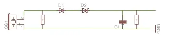
Here is my attempt at a schematic. I've just downloaded Eagle and am not entirely sure how to use it, but hopefully this is close enough to give the idea. The piezo symbol on the left doesn't look right to me, but that's what Eagle gave me.

schematic

EDIT #2:

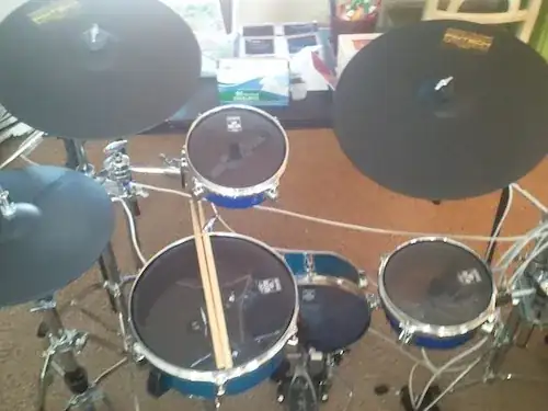
Per several requests below, here are some pictures of my circuit (slightly updated from several peoples suggestions). Also, I've included some pictures of the drums. The drums use a special "screen" drum head that makes very little audible sound. There is a small piece of foam that transfers the drum head vibrations to the piezo.

Breadboard Circuit Drum Set Single Drum

herbrandson
  • 181
  • 5
  • A schematic would be very helpful. As it is you're asking everyone who reads this to reconstruct the schematic from your text description of the circuit. Frankly, nobody is going to bother to do that. – The Photon Jun 25 '12 at 16:19
  • Please add a proper circuit diagram, this is rather hard to follow! There might be milage in having a smaller voltage divider to match the input to the output; note that if the input voltage went over the 3.3V it would probably cause problems on the Netduino. – pjc50 Jun 25 '12 at 16:19
  • 2
    Second, a photo of the circuit as built would be very useful for us to see if there's any way the construction could be causing crosstalk issues...That said, I'm with StevenVH, acoustical crosstalk seems more likely than electrical. – The Photon Jun 25 '12 at 16:20
  • Thanks for the feedback everyone. I've attached a crude schematic. I hope that helps. I'll try to add a photo later this evening. – herbrandson Jun 25 '12 at 16:50
  • It looks like either your Zener or your Schottky diode is connected wrong way 'round. A Zener produces a fixed voltage drop when current is going *in* to the cathode and coming *out* of the anode. When hooked up the other way, it behaves like a normal diode (roughly 0.6 to 0.7 V drop). – The Photon Jun 25 '12 at 16:54
  • The zener should probably be reversed. But then it doesn't protect. If you play the drum so hard that the piezo gives 10 V, then you'll still have 6.7 V on the Netduino's input. Even more, because the zener's voltage will be much lower at low currents. Also low level signals won't even reach the Netduino. Solution: place the zener parallel to the input, not in series. – stevenvh Jun 25 '12 at 17:09
  • How are your wires bundled, and how are all the GNDs interconnected? – Martin Thompson Jun 26 '12 at 09:51
  • If you are wanting to draw schematics I suggest that you use [circuitlab](http://circuitlab.com), it can be very helpful, but that is tangent to the discussion going on here. – Kortuk Jun 26 '12 at 15:41

3 Answers3

8

A real schematic would help!!

I don't think the crosstalk is something in your circuit, but rather is acoustic. The other drums act as microphones and pick up the vibrations of the drum you're playing. The only solution I see is to add antisound to the other drums' signal, but that requires that you have a very good idea of the amplitude and phase of the signal you want to cancel.

edit (re your comment)
If hitting a disconnected drum doesn't give you crosstalk, then it doesn't seem to be acoustic after all. I want to have a look at your wiring. The signal should be a high peak voltage (high dV/dt), followed by a quickly decaying sine (the drum's resonance). If the wires between drums and microcontroller are very long and very well coupled (like intertwined), with the high impedance you have this may cause minor crosstalk. Not so much from the resonance sine wave, but from the fast peak when you hit it. But this should only give a small "tick" sound, not the typical drum.
So how did you wire it up? Try to use separate wires for each drum.

stevenvh
  • 145,145
  • 21
  • 455
  • 667
  • Thanks for the response. I've attached a schematic that will hopefully help some. – herbrandson Jun 25 '12 at 16:53
  • Agree that it's mechanical coupling that is the likely culprit. Figuring out a way to dampen / isolate the propagation of vibrations between drum pads – vicatcu Jun 26 '12 at 04:24
  • I doesn't look like this is an acoustics issue. Per the suggestion of @fceconel below, I tried disconnecting one of the drums and seeing if I still get the crosstalk. The result is that the crosstalk only happens when the drum is connected. In other words, if I hit a drum hard (while it's connected) I get crosstalk. If I disconnect that same drum and hit it hard again, no crosstalk. Connect that same drum again and hit it hard and the crosstalk comes back. I think that rules out this being an acoustic issue. Do you agree? – herbrandson Jun 26 '12 at 04:30
  • I've added some photos that show the actual wiring. Is that what you're looking for? – herbrandson Jun 26 '12 at 16:22
6

I'd recommend to change the zener placement as shown to have the effect you intended; this has nothing to do with your problem, though.

As stevenvh mentioned, it's improbable that you have electric crosstalk from such an arrangement, but if you want to be sure a shielded cable from the drum to the arduino would help. But in the most probable case, in which it's an accoustic effect, consider dealing with the problem in software. It's almost impossible that you hit two drums at exactly the same time, even if you're using both hands to hit simultaneously two different drums. So how about simply considering as a valid hit at any given timeslice only the strongest input, and ignoring the others?

BTW, to confirm that the problem is really accoustic, try to disconnect one drum and hit it to see if it still produces an input in the other (connected) drums.

schematic

EDIT: revised according to comment below enter image description here

fceconel
  • 2,659
  • 22
  • 19
  • I don't think that is what the zener was intended to do. It is a good idea to clip the result to make sure the A/D range isn't exceeded, but I think the zener was there to set the minimum level at which a drum hit is detected. It was in the right place for that, just backwards. Also, for clipping, I would put the zener after D2. – Olin Lathrop Jun 25 '12 at 18:25
  • 2
    But in the question he says "Zener should be making sure I'm not getting anything above the 3.3v that the Netduino wants", right? – fceconel Jun 25 '12 at 18:32
  • You're right about the placement, indeed. Correcting. – fceconel Jun 25 '12 at 18:45
  • The OP's statements are conflicting. I suspect he saw a schematic with the zener in series and accidentally flipped it, the supposed a different purpose for the zener. In any case, thresholding for the minimum require drum hit is best done in the firmware. – Olin Lathrop Jun 25 '12 at 20:42
  • The intended purpose of the zener is indeed to clip the signal to no more than 3.3v (the Netduino max). The minimum threshold is already being handled in software. – herbrandson Jun 25 '12 at 20:48
  • I've tried disconnecting a drum and hitting it, but then I don't get any crosstalk (see my comment on @stevenvh's reply). So, it seems to not bean acoustic issue. I've also tried altering my circuit per your suggestion. Now I don't get crosstalk, but I also never get a reading of over half the analog pins max value. These results are similar to what I get if I put a voltage divider at the end of the circuit. – herbrandson Jun 26 '12 at 04:40
  • I'd suggest adding a transistor (any cheap NPN would do, like the BC547) and a trimpot to find the desired gain. After that you can replace the trimpot by a fixed resistor. Check out the edited schematic. – fceconel Jun 26 '12 at 13:56
  • BTW, what's the specific zener p/n you're using? – fceconel Jun 26 '12 at 13:58
  • @fceconel Sorry for being a total noob, but I'm not 100% sure what p/n means. I assume it's part number. If so, the zeners are NTE5066A, purchased at my local Frys Electronics :) – herbrandson Jun 26 '12 at 16:05
  • It's OK, sorry too for using an abbreviation, I was indeed talking about the part number. I checked out the spec at http://www.nteinc.com/specs/5000to5099/pdf/nte5061a.pdf and it seems that its max impedance is significant (1.2M) considering it's effectively in parallel with your piezo and the other two resistors. So maybe it would be necessary to increase the value of the resistors to compensate that, but I think using the transistor may be a better option, if you place it and the other components near the drum, for better immunity to noise. – fceconel Jun 26 '12 at 22:46
  • @fceconel I've been out of town for a few days and haven't been able to try this out yet, but I do have a quick question. Since I'm connecting to a Netduino which has an ADC max of 3.3v, would the BC547 work? The datasheet I found says it's trigger voltage is 5v. Also, I'm not entirely clear how the transistor is working in this schematic. I get the basics of how an NPN transistor works, but I don't see how that's helping here. Is there a term for this use of an NPN that I could google to learn more? – herbrandson Jun 30 '12 at 22:06
  • From what I saw, the change in the position of the zener removed the noise because below 3.3V it is acting as another 1M resistor in series with the piezo, thus reducing the overall resistance connecting the piezo output to the ground. The transistor would act here as an amplifier, the base-emitter current would produce a colector-emitter current multiplied by the gain, adjustable by the trimpot. The "current" I refer is not literal, since the ADC has high impedance, but the equivalent C-E resistance will produce a voltage to the ADC equally multiplied. – fceconel Jul 01 '12 at 01:24
  • Another thing you could do is to increase the value for the other resistors in the circuit, but I'm guessing when you arrive at the original total around 300K the crosstalk will be back. Perhaps there's a middle ground, you'd have to try. – fceconel Jul 01 '12 at 01:30
3

I think your trigger level for deciding a drum was hit is too sensitive. You need some level below which you figure the drum was not intentionally hit. That is probably what the zener in your circuit was intended to do, but you have it wired backwards so that it only adds a small threshold instead of the over 3 V as intended.

However, a zener is rather a hack for thresholding. You say this is going into a microcontroller, so I would lose the zener altogether and do the minimum thresholding in the micro. This is assuming that a maximum whack results in just about the full A/D voltage range. Adjust the second resistor (next time put component designators in your schematic) to get the right maximum volume, then adjust the firmware to ignore peaks below a certain level.

Olin Lathrop
  • 310,974
  • 36
  • 428
  • 915