2

I am trying to make a basic EPROM programmer using an Arduino. It is designed to programme M27c322/160/800 devices.

One problem I am encountering is that these 3 devices have a couple of the pins different. For example, the A20 pin on the 322 is actually the BYTE pin on the 160/800. This means that my Arduino will need to be able to switch this pin between a digital address signal line and a power line that supplies 12V at something like 100mA, depending on which chip is being programmed.

What is the best way to do this?


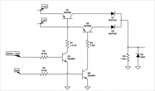
EDIT 3 - OK so I've had a go at this based on the answers I've already had, does this work as intended?

So basically with the APPLY_A20 line low, the mux just shows a floating pin to the rest of the circuit, allowing me to assert APPLY_12V or APPLY_5V to get power, then if I need to use the A20 address then I pull the APPLY_12V and APPLY_5V lines low and assert APPLY_A20 high.

enter image description here

Jaska
  • 57
  • 6
  • Suggest you re-word "It is designed to programme M27c322/160/800 *roms*" before the others get here :-) – TonyM Dec 14 '17 at 10:46

2 Answers2

2

For a programmer you really need to be able to turn on the various control voltages AND have the ability to isolate the pin for insertion and removal. Also, since there are fingers involved, you also need some ESD protection.

As such, at least three control pins per device pin is not unusual.

schematic

simulate this circuit – Schematic created using CircuitLab

Of course, care has to be taken to ensure only one of the inputs is ever active at any one time.

Some devices also have other voltage requirements and a more complex circuit can be required.

schematic

simulate this circuit

ADDITION

A further must have, or at least REALLY NICE TO HAVE is a sniffer circuit on the Vcc pin that stops the programmer from applying power when the device is inserted upside down. A really good programmer will include circuitry on all pins in case the selected part <> the actual part.

ADDITION 2

If you want do feed A20, wherever THAT comes from, you can use this circuit, ensuring A20 is low when you apply the 12V.

schematic

simulate this circuit

Trevor_G
  • 46,364
  • 8
  • 68
  • 151
  • Hi Trevor, thanks for the detailed response. Regarding your top circuit, that's a nice handy way to switch between voltages, but can I expand it to allow me to control the EPROM pin with an address line that will be pulled both high & low? I imagine that I could have an additional MCU pin that switches the control between the voltage selection circuit you describe and a digital address signal, but I am unsure how to implement that. – Jaska Dec 14 '17 at 23:14
  • Do I simply add an extra 2N3906 to the top of the schematic, with my digital address signal (so +5V or +0V depending on the address being asserted) on the left side of it, with that being controlled in the same way as the others (i.e. with a MCU signal and a 3904 to turn the transistor on)? Hope that made sense, I can draw it up tomorrow and post it if not. – Jaska Dec 14 '17 at 23:18
  • One last quick question, what is turning the 3906 PNPs off? Don't you need pull ups on the bases? – Jaska Dec 14 '17 at 23:21
  • @Jaska theoretically you could tie the address pin into APPLY_HI and leave the apply gound out if you add a pulldown to the driven pin. Pulllups on the bases of the PNPs would not hurt but in reality, as long as no current is being pulled they wont leak much. – Trevor_G Dec 14 '17 at 23:38
  • Trevor, would there be any problems with having an address line going through a 10k resistor to the base of the transistor? Is there an issue with the response of the system to the address line changing high/low? – Jaska Dec 15 '17 at 06:14
  • Another quickie, you say "tie the address pin into APPLY_HI", I'm assuming you don't mean I can have two MCU pins tied together (a 5V enable and an address line)? Is it best that I have a 5V enable line that is pulled high when I want +5V of power and also whenever the appropriate address line is high? That would be easy to implement in my software. – Jaska Dec 15 '17 at 06:22
  • I have added my idea for it above, let me know what you think. I idea being that I can give control of the EPROM pin by asserting APPLY_A20 high with the other APPLY lines low. Would it work this way? I have added the pull-down as you said, hopefully I did it correctly. – Jaska Dec 15 '17 at 08:18
  • @Trevor, or anyone, what are D1 and D2 are for? – Mike Dec 15 '17 at 17:59
  • @Mike the diodes prevent current from flowing back into the collector of the PNPs, especially for Q2 which can in one mode feed the 12V back onto the 5V line. – Trevor_G Dec 15 '17 at 18:04
  • @Trevor, is that only for a scenario where both "Apply_12v" and "Apply_5v" are asserted high at the same time ? Perhaps I should open a separate question for that ? – Mike Dec 16 '17 at 12:32
  • 1
    @Mike no if the 12V is on the Q2 would act in reverse mode putting a high reverse voltage on the base emitter junction. – Trevor_G Dec 16 '17 at 12:56
  • @Trevor any comments on my schematic I posted above? It's similar to the one you suggested but with the A20 control circuitry added. – Jaska Dec 18 '17 at 09:35
  • @Jaska see addition 2 – Trevor_G Dec 19 '17 at 17:24
  • @Trevor thanks :-) If I need also a dedicated +5V line (separate from the A20 line), can I just have another 3906/3904 pair on the +5V rail in parallel with the one for the A20 line? Obviously it will need another diode, maybe the BAT54TW with the cathodes tied together will work? – Jaska Dec 20 '17 at 06:55
  • @Jaska sure that will work too – Trevor_G Dec 20 '17 at 13:11
  • 1
    @Trevor great, thanks for all your help. I appreciate it :-) – Jaska Dec 20 '17 at 13:26
1

I would use an electronic SPDT (like 1P1G3157QDCKRQ1) to select between a power control or a signal (comm) line. Here's an example:

schematic

simulate this circuit – Schematic created using CircuitLab

CTRL pin selects the terminal that COM is connected to. In the UP position, COM pin enables the power through Q2 power transistor to the chip. In the DOWN position, power to the chip is disabled and COM line can be used a digital communication line.

Rohat Kılıç
  • 26,954
  • 3
  • 25
  • 67
  • You cant put 12V on the right side of that switch – Trevor_G Dec 14 '17 at 12:09
  • @Trevor You mean that one of the terminals of G3157 can be 12V for easier selection? If so then no it cannot, because G3157's max VCC is 5V and max terminal voltage can be VCC. – Rohat Kılıç Dec 14 '17 at 12:27
  • @Yup. which is what you have – Trevor_G Dec 14 '17 at 12:30
  • 1
    @Trevor Oh, I got it. Sorry :) Thanks for noticing. – Rohat Kılıç Dec 14 '17 at 12:34
  • Now you cant pull it low... – Trevor_G Dec 14 '17 at 12:39
  • @Trevor Sorry but still I couldn't get why you downvoted this. What's wrong with the circuit above? Can you detail please? If it's about the risk of applying +12V directly to the G3157 then I've fixed it via a schottky or 4148. – Rohat Kılıç Dec 14 '17 at 13:00
  • I down-voted originally because it would blow up the switch. Now you added the diode that is no longer the case, however, now you can not assert a logic low to the pin. – Trevor_G Dec 14 '17 at 13:02
  • 1
    @Trevor Ah yes, you're right. So a pull-down resistor would do the job. I intentionally didn't put it originally because the pin's input impedance can hold the line at 0 internally. Anyway, fixed. Thanks again. – Rohat Kılıç Dec 14 '17 at 13:08
  • Hi Rohat, thanks for a detailed answer. This seems to be a nice solution that I will consider. Can I combine this solution with Trevor's voltage selection so I can exchange control between his voltage selection and the digital address line? In other words, basically replacing where you have the +12V port with the output of Trevor's circuit? – Jaska Dec 14 '17 at 23:26
  • @Jaska You're welcome. Yes, you can as you described. But please note that the voltage at POWER line will be approximately 1V less than desired because of two VCE(sat) plus two schottky diode forward voltage. – Rohat Kılıç Dec 15 '17 at 03:51