11

Can someone explain more about how you generate data for flexible or flexi-rigid PCBs for manufacture? Do I just make more layers and export more gerber files? Is there anything I need to keep in mind when sending these to be manufactured?

I've made a decent number of medium-complexity 2-layer boards and had them manufactured by producing gerber files. I use Pulsonix, but am familiar with Eagle as well.

AlcubierreDrive
  • 1,484
  • 2
  • 18
  • 26
kerblogglobel
  • 283
  • 4
  • 9
  • 5
    Your fab could answer your questions easily. Give 'em a call. Look into this too: [Flex Circuits Design Guide](http://www.minco.com/uploadedFiles/Products/Flex_Circuits/Technical_Specifications/FC302.pdf). – Nick Alexeev Jun 22 '12 at 05:11
  • 4
    Rigid boards are pretty standardized, but flexible circuits can be made in lots of different ways. So definitely talk to your fab. – markrages Jun 22 '12 at 16:02

3 Answers3

8

Mostly the same stuff as for rigid FR4 boards. Material will often be polyimide or polyester. Of course you'll want to bend the PCB, so check with the manufacturer what the minimum bend radius is for different thicknesses. In general this radius is small, like 6 to 10 times the circuit's thickness for a double layer FPC, that's a couple mm, and shouldn't be a real limitation for most applications.

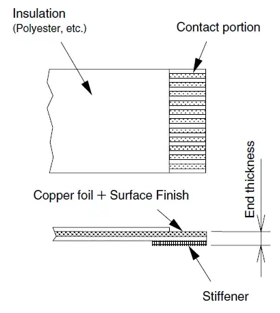
Provide drawings of stiffeners, and their material (often FR4). Also of contact areas, with data on finishing (like gold, and its thickness).

enter image description here

stevenvh
  • 145,145
  • 21
  • 455
  • 667
4

A flexible PCB is just a one- or two-layer device with a different material specification (polyimide instead of some sort of FR4). The Gerber files are no different.

Flex-rigid-combinations are similar: You'll give them a pretty regular Gerber stack, as with rigid PCBs.

In addition, you send them a specification for the layer stack and tell them which layers are to be fabricated on polyimide. Flex in the middle or your stack? Flex on an outside layer? An additional Gerber layer with the dimensions for the entire PCB and the parts that are flexible might help.

Note (a): Talk to your PCB shop. They will let you know what specification will work best for them.

Note (b): A specification of the stack including all the details is a good idea even for rigid two-layer or multi-layer boards: Tg of the FR4, thickness of the individual FR4 cores and prepregs, finish (HAL, ENIG, ...) copper thickness for each layer, ...

zebonaut
  • 18,170
  • 4
  • 60
  • 104
3

I am not a PCB design engineer, but I am working in PCB industry.

To manufacture a board, we generally require Gerber data. We will need the following:

A gerber layer for every physical layer, including solder masks, and an NC drill file with drill tool sizes. Excellon format is the most common drill file format.

Gerber data should be in ASCII format, preferable in imperial units, with a preferred precision of at least (2,4). The drill file should be the same precision as the gerber data. We can use RS274D data with an aperture table, but RS274X is preferred, as it is the latest standard. Metric units are acceptable with a preferred minimum precision of (3,3)

A readme file and fab drawing are recommended. A sample readme.txt file is available. If the board is multilayer, we will require the layer order. The readme should also have any other information not in the file set, such as material type, copper thickness, etc...

All the data files should be put into a single archive file, *.zip files are the most common. We need this for error protection for anything sent through the internet. It's best to name the *.zip file after the part number of the board (ie LCDDriver.zip)
Kortuk
  • 13,362
  • 8
  • 60
  • 85
Kevin Lau
  • 47
  • 2
  • 5
    This is exactly the same data required for rigid PCB manufacture. Are there any differences that are worth mentioning? – markrages Jun 22 '12 at 16:03