4

I have a small motor what operates at 3.3V at 50mA (sorry no documentation) and a Xbee radio which outputs 1mW.

I would like to allow the Digital I/O pins output on the Xbee to drive the motor though it is currently to weak. I've thought of these two solutions though I need help on either of them.

  1. The Xbee Documentation says the 1mW output is "software selectable." I have XCTU which I've been using to get the Xbee's to talk. Is there an option is XCTU to change the Xbee's output to >1mW ?

  2. Design a amplifier. I thought that maybe using a simple amplifier curcuit might work. I'm just not sure how to amplify the 1mW signal properly.

Kortuk
  • 13,362
  • 8
  • 60
  • 85
Mike
  • 583
  • 1
  • 7
  • 17
  • 7
    Are you perhaps confusing a 1mW RF output with the power handling capability (traditionally more likely to be expressed in mA at a voltage) of the digital output pins? – Chris Stratton Jun 21 '12 at 15:35

2 Answers2

9

It's most likely you are confusing the RF output power with the digital outputs as Chris notes . In any case it's unlikely the outputs will be able to source/sink 50mA (usually <20mA) Their current capability should be mentioned in the datasheet though.

EDIT - I checked the datasheet which confirms the 1mW transmit (i.e. RF comms) power, but I can't find a current sink/source value for the digital pins. So with no specs to follow you have no choice but to assume they are not capable (edit - as Steven notes there is mention of a 2mA test condition for the max low/min high outputs, so this figure is likely to be the nominal source/sink rating)
EDIT 2 - I just came across this 2010 version of the xBee datasheet (I think it describes the same hardware) which has the necessary information added - they say:

The combined source and sink capabilities of the module are limited to 120 mA for all pins on the module. Module pins 11 and 15 can source/sink a maximum of 2 mA; pins 9, 6 and 13 can source/sink a maximum of 16 mA; all other pins can source/sink a maximum of 8 mA.

So there you have it, none of the IOs can handle 50mA.

This means you will need a simple transistor to handle the current. Something like this should do:

Motor driver

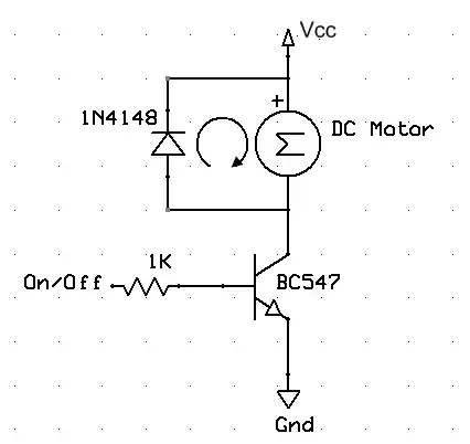
The NPN can be pretty much any "general purpose" transistor, and the diode can be changed for a similar part also. If you use one of the low current I/Os (pins 11 or 15) you'll have to increase the base resistor to 1.5 kΩ.

Suitable transistors:

As mentioned the BC337 or BC817 is an excellent, cheap, high gain general purpose transistor. To find more, have a look on a site like Farnell and use the very useful parametric search. For the parametric search input, we know we need an NPN transistor capable of 50mA and 3.3V (pretty much anything)
The only possible issue is the gain - since the xBee pins are low current, the higher the gain the better (we can use a higher value base resistor and save power). So if we select NPN, and then order results by hFE (current gain) we get a few pages of darlingtons at the top, then on page 9 we start seeing standard bipolars with gains of ~800.
For example the 2SD2114KS has a minimum gain of 820, so to get 50mA we need 50mA / 820 = 61uA. If we use say 200uA to be "safe" we can have a base resistor of (3.3V - 0.7V) / 200uA = 13K.
In reality this is a bit overkill and a BC337-40 or similar with a minimum gain of 250 would be fine (with e.g. a 5k resistor on base)

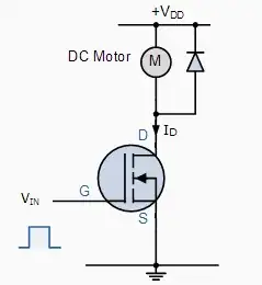
A suitable logic level MOSFET will do the job too as per Stevens answer, you just have to make sure the gate threshold voltage (Vth) is low enough to allow your drive signal to turn the MOSFET on adequately.
A possible issue if you are wanting to use through hole is there is not a good selection of decent logic level MOSFETs in e.g. TO-92 packages. If we apply the parametric search again, we need the same current/voltage rating, but now we need to look for a part with a threshold voltage well below 3.3V.
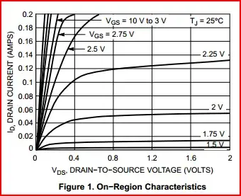
I say well below as Vth only indicates when the part begins to turn on, and will only pass a few uA at this level. To get the full story we usually need to look at the gate voltage versus drain-source current graphs.

So we search for: N-channel, continuous drain current >100mA, drain-source voltage >5V (to cover the 3.3V) and threshold voltage Vgs typical of <1V. There are thousands of results, but we still need to check in the datasheet just to make sure the MOSFET will be sufficiently turned on at 3.3V.
Something like the NTS4001N has a max Vth of 1.5V and according to the graph (see below) will pass ~130mA at a Vth of 2.25V. It has a pulse current of 800mA which should handle the motor startup surge.

Vgs vs Ids

Oli Glaser
  • 54,990
  • 3
  • 76
  • 147
  • will the motor limit current itself? – miceuz Jun 21 '12 at 22:03
  • 2
    Yes. The motor windings have internal resistance and as the motor turns a back EMF is generated also limiting the current. This is why the motor will draw a lot more current when stalled or starting up. – Oli Glaser Jun 21 '12 at 22:11
  • 1
    @Oli - On page 8 of the datasheet the maximum low and minimum high outputs are given at 2 mA, so I think that will be the nominal value, for lack of a better spec. – stevenvh Jun 22 '12 at 15:06
  • @Steven - Well spotted, I agree that's probably a fair assumption to make. – Oli Glaser Jun 22 '12 at 16:24
  • 1
    @Steven - Just found [this later version of the datasheet](ftp://ftp1.digi.com/support/documentation/90000991_B.pdf) whist looking at [this question](http://electronics.stackexchange.com/questions/34402/xbee-and-pir-sensor), which has the IO current specs on page 7. – Oli Glaser Jun 22 '12 at 21:42
  • Thank you, this is very helpful. What are some general purpose transistors that I could buy. Would I want to just go with the BC547 – Mike Jun 28 '12 at 22:19
  • There are many to choose from, but I use BC337 and BC817 (SMD version) frequently as a general purpose NPN. The BC337 is a 45V, 500mA TO-92 comes in three gain options, BC337-16 (max gain 250), BC337-25 (max gain 400), and BC337-40 (max gain 600) Where do you intend to buy from? If you let me know I'll have a look what they have that suits and edit the answer. – Oli Glaser Jun 28 '12 at 23:00
  • @Oli - maximum gain is hardly ever relevant, it's minimum gain that counts. That's always specified, while maximum often isn't. – stevenvh Jun 29 '12 at 09:12
  • @Steven - yes, you're right - I was just outlining the fact that the part can very widely, so the min/typ/max would do (to be thorough maybe all three). In the answer example I go from the minimum gains. – Oli Glaser Jun 29 '12 at 10:06
3

Oli is a nice guy and such, but a BJT to switch a motor is so 2011! :-)

Especially since a few of the XBee's outputs can drive only little current (2 mA) a FET may be a better choice as a switch. Unlike a BJT, which is current-controlled, a MOSFET is controlled by a voltage on the gate.

enter image description here

Since you're working at low voltage you'll need a logic FET, which can switch at low input levels. The BSS806N has an on-resistance less than 57 mΩ and can switch several amperes at just 2 V gate voltage. The low on-resistance means that the device won't heat up at even 1 A.

You need the diode over the motor, just like with the BJT to protect the transistor against back-EMF. A Schottky diode is preferred, a BAT54 will do nicely.

stevenvh
  • 145,145
  • 21
  • 455
  • 667
  • Meh, you always know where you are with a good old BJT. I guess these MOSFET things have their uses too though ;-) – Oli Glaser Jun 28 '12 at 23:12