6

I am fairly new to electronics, so please pardon my mistakes.

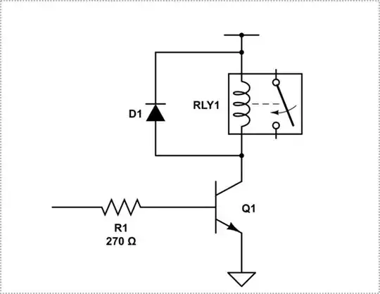
I am attempting to build a Wi-Fi controlled relay. The problem, however, is that the relay runs on 5 V, but my ESP-12E can only supply 3.3 V. I figured to connect the (+) end of the relay to the VCC (5 V input) and then the GND end to a transistor which also connects to ground. The base of the transistor is connected to my ESP-12E's 3.3 V GPIO output. Here is what my circuit looks like:

Nick Alexeev
  • 37,739
  • 17
  • 97
  • 230
Jeebus
  • 91
  • 5

4 Answers4

23

You are pretty close, except your transistor is upside down. You should also add a diode across the relay coil contacts to avoid back EMF and a resistor on the base of the transistor.

schematic

simulate this circuit – Schematic created using CircuitLab

Something else I noticed...

It looks like you are trying to power your ESP through a resistor divider? That is a bad idea, the current through the divider depends on the draw of the circuit which can alter the amount of voltage fed into the ESP. Generally resistor-dividers are OK for measurement purposes, but do not use them to adjust power or as a step-down power supply.

Ron Beyer
  • 2,568
  • 1
  • 8
  • 22
  • The VCC is coming from an AC to DC converter that has a constant 5v output, thus I figured a voltage divider would be a nice and compact way to step down the voltage from 5v to 3.3v. – Jeebus Dec 01 '17 at 03:31
  • 4
    It isn't, a linear regulator is the way to go here, not a divider. The voltages are close enough that you wouldn't need a buck converter, linear is fine, but a voltage divider will not do what you want it to. Think of your ESP as another resistor whose value changes depending on the draw, which can vary wildly on that chip due to wireless transmissions. – Ron Beyer Dec 01 '17 at 03:39
  • Shouldn't the diode be reversed since electrons flow from (+) to (-) and you want to stop backfeed? – Jeebus Dec 01 '17 at 04:15
  • 4
    No, it's correctly placed. I'd suggest reading up on flyback or "catch" diodes and if you are still confused on how it works, ask a new question on here. – Ron Beyer Dec 01 '17 at 04:19
  • 2
    @Jeebus If the diode would have been as you say, anode at top and cathode at bottom. Then when you try to activate your relay, most of the current will go through the diode instead. And then when it closes, all the energy stored up in the inductor in the relay has nowhere to go and you will get high voltages (can be 100 volts, or more). If you instead attach a diode in the configuration as Ron has shown, then the current will flow through the relay as you want, and when you turn it off the current will safely slow down through the diode when you turn the relay off. Much information, yeah.. – Harry Svensson Dec 01 '17 at 04:39
  • I understand. Thank you for the awesome feedback, you definitely deserve an upvote. – Jeebus Dec 01 '17 at 04:47
  • @Jeebus - the way to think about the voltage divider is that your ESP-12 module itself has a resistance between its VCC and GND pins that you're placing in parallel with your R2. This resistance will alter the effective resistance of R2 and cause the divider to produce the wrong result. What's worse is that that resistance will *change* according to what the module's doing at the time. – Jules Dec 01 '17 at 19:03
  • FTR, a resistor-divider _can_ offer a quite stable voltage, provided you always let much more current float through the resistors than through the device to be powered. Of course that means you waste more power than you actually use, but when the power you need is very low this may still be quite ok (e.g. for an analogue JFET preamplifier it can actually be preferable, because you don't introduce any switching whatsoever that might bleed into the signal). As soon as you power anything digital I'd agree, a buck converter or linear regulator should be used. – leftaroundabout Dec 02 '17 at 11:50
12

You are close.

Your transistor is upside down and you need a base resistor. You should also add a fly-back diode to protect the transistor.

schematic

simulate this circuit – Schematic created using CircuitLab

As Ron spotted, you can not divide down the voltage like that to power your module, You should use an appropriate 3.3V LDO Linear voltage regulator.

Trevor_G
  • 46,364
  • 8
  • 68
  • 151
  • 1
    +1 pretty much exactly what I put, just quicker on the draw (quite literally)... – Ron Beyer Dec 01 '17 at 03:13
  • @RonBeyer ya I was not sure what that thing can source though or what the relay needs.. – Trevor_G Dec 01 '17 at 03:14
  • 1
    Take a look at the resistor-divider on the VCC side too, probably worth mentioning and you can probably explain why you shouldn't do that better than I can. – Ron Beyer Dec 01 '17 at 03:17
  • 1
    @RonBeyer lol, oh dear.. well at least he won't need the base resistor.... ;) – Trevor_G Dec 01 '17 at 03:29
  • @Trevor I noticed your resistor is rated at 270 Ω but the poster above rated his at 1k Ω. I looked at the data sheet for a standard 2n2222 transistor, but I didn't see anything describing the base voltage. Could you explain why you chose 270 Ω? – Jeebus Dec 01 '17 at 22:43
  • @Jeebus I guessed at a higher relay coil current... – Trevor_G Dec 01 '17 at 23:01
3

You can google it.

  • You are missing a resistor between your ESP and the base of 2N2222
  • The 2N2222 is also upside down
  • The relay is missing a fly-back diode
Null
  • 7,448
  • 17
  • 36
  • 48
Harry Svensson
  • 8,139
  • 3
  • 33
  • 53
  • Sorry, I am new to stack exchange. You're right that I should not have deleted it. Thanks for the comment though- I want to say that I have been googling this for a while and seeing different responses to this setup. – Jeebus Dec 01 '17 at 03:29
1

Your 2N2222 is oriented with the emitter connected to VCC, so the PN junction from base to emitter will not conduct with GPIO16 in either state.

Think carefully about the structure of the NPN transistor and you'll see how you can protect the GPIO pin and switch the relay.

i3070
  • 11
  • 1
  • 1
    Actually it might as shown, at least for a while. The base current will likely be some tens of mA and the transistor may have enough reverse beta to pull the relay in. When it drops out the ~90mA coil flyback current will Zener the E-B junction at less than 10V, probably scuppering the beta long term. – Spehro Pefhany Dec 01 '17 at 05:48