4

I have a bicolour RG LED, which looks like this:

RG LED.

I don't have a datasheet for it. There are three cables on it: one is cathode of each colour (common cathode type) and the other two are the anodes of each colour. The forward voltage of each LED is 24V, and forward current is 10 mA.

I want to change its colour by changing ONE digital output of an arduino. I mean that when the digital output is low, green LED is on, and red LED is off. And then when the output is high, green LED should be off, while the red LED is on. Digital output level is 3V DC when it's "high" state, and "0" V DC when it is "low" state.

So, how can I control which LED is on, while changing one digital output?

ad555
  • 133
  • 8
cem mortas
  • 81
  • 1
  • 5
  • 2
    What do you *think* would solve this? This can be solved **very easy** with boolean algebra. – Harry Svensson Nov 27 '17 at 21:43
  • Well, you could wire it so when it has power it is always green, and then under control of the one arduino output, change it to yellow, but this is probably not what you wanted. In short, with only one output, not even charlieplexing can help you here. – Glen Yates Nov 27 '17 at 22:36
  • @GlenYates a good alternative, but as the answer shows, it's possible with a single output. – Passerby Nov 27 '17 at 23:55

2 Answers2

20

schematic

simulate this circuit – Schematic created using CircuitLab

Figure 1. High-side driver and inverter.

How it works:

  • If GPIO is low then Q1 is off and Q2 is off. Q3's base will find a path to ground through R1 and D1 and will turn on lighting D2.
  • If GPIO is high then Q1 is on, Q2 is on and D1 will light. Since the collector of Q2 is pulled high Q3's base current will fall to zero and D2 will turn off.
  • By using PWM (pulse width modulation) the light can blend from one colour to the other.

Does it have to be so complicated?

enter image description here

Figure 2. High-side driver fail.

Yes. Without the NPN transistor of Figure 1 there are two problems:

  1. There is a sneak path for the current through the protection diodes of the micro's GPIO. Whether the output is pulled high or tri-stated to try to shut off the PNP transistor of Figure 2 the base can turn on via D1.
  2. The high voltage - 24 V in your case - may damage the GPIO.

Opto-isolator option:

enter image description here

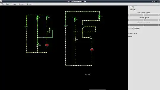
Figure 3. A pair of opto-isolators simplifies the task further and can isolate the 24 V circuit completely from the micro.

  • When the GPIO is low the upper opto-isolatore will be turned on.
  • When the GPIO is high the lower one will be turned on.

The very simple option:

The LED series resistors are clearly visible heat-shrunk in leads of the lamp. If you are prepared to replace these the circuit becomes trivial.

enter image description here

Figure 5. Direct drive of the LEDs.

Setting R1 and R2 to 56 Ω should be fine.

If the output is tri-stated (wired as an input or disconnected by program control) a current will flow through R1, L1, R2, L2 and both LEDs will glow dimly. On a 3.3 V device the voltage wouldn’t be high enough to illuminate both LEDs significantly so they would appear dark.

Transistor
  • 168,990
  • 12
  • 186
  • 385
  • 1
    Looks like there is only one low side resistor – Passerby Nov 27 '17 at 22:39
  • Sure. Looks like it could use a pull up between q1 and q2. – Passerby Nov 27 '17 at 22:55
  • I've seen the pull-ups used before but never understood the risk without the pull-up on the base. Can you explain. – Transistor Nov 27 '17 at 22:57
  • @Transistor Without it, there's no DC path to completely tie base and emitter (unless you want to call the PN junction a DC path.) There's charge storage, remember? Also, it's also for speed due to that charge storage. And it's high impedance otherwise and can be affected by things like "touching it." See: [Why pull base of BJT switch?](https://electronics.stackexchange.com/questions/56010/why-pull-base-of-bjt-switch), for another's perspective. I use them. They are cheap and effective. – jonk Nov 27 '17 at 23:06
  • I've added an 18k pull-up. Everyone happy? Thanks for the time, chaps. – Transistor Nov 27 '17 at 23:15
  • @Transistor What about \$Q_3\$ and \$Q_1\$? And, well, every node should have both a pull down and a pull up on it. And may as well add BAV99 diode protection at the bases and maybe collectors, too. ;) – jonk Nov 27 '17 at 23:50
  • Hi, @jonk. My opto-isolator solution is looking better and better! Does Q2 not adequately shunt the base of Q3? (It's lights out time in Ireland.) – Transistor Nov 27 '17 at 23:53
  • @Transistor \$Q_2\$ is an active pull, so probably not. I was mostly teasing. I would add one on \$Q_1\$, though, because microcontroller pins start out as inputs before the software can reconfigure them. (Ah. My homeland! O'Quirivan family name! ) – jonk Nov 27 '17 at 23:56
  • @jonk Q3 doesn't need one. It's either pulled hard up through Q2, or low via the led. At no point is it ever floating. Q1, well, unless the Arduino is off while the 24V supply is on, in high-z, or disconnected, sure. – Passerby Nov 28 '17 at 00:00
  • @Passerby Just as I wrote. No disagreement at all. – jonk Nov 28 '17 at 00:01
  • Actually, wouldn't Q3, through the green led, always be slightly on? I simulated it (r1 and r2 should be about 2kΩ) and the green led + resistor have 3.6V and 1.3mA across it when the GPIO is low. So this is really yellow tinted red/pink and green. – Passerby Nov 28 '17 at 00:14
  • 1
    I would go with the opto-isolator solution. Nice and clean. +1 on that one. – dreamcatcher Nov 28 '17 at 03:00
  • This could also be done with an h-bridge driver chip that uses mosfets. – kjgregory Nov 28 '17 at 16:57
  • Hi. In the first schematic you use 1 NPN and 2 PNP transistors. Why is that? What are the benefits? – user1584421 Dec 02 '17 at 13:03
  • @user1584421: See the [GPIO high-side driver fail](http://lednique.com/gpio-high-side-driver-fail/) article. Let me know if that helps. – Transistor Dec 02 '17 at 13:05
2

I'm not sure if I understood your question correctly, but if I did, then the easiest answer is to use a not gate.

Take the output from the Arduino pin, tap into the output using a not gate, and then connect the two LEDs.

When the output is high, the LED connected directly to the output lights up while the other one doesn't. When the output is low, the LED connected to the not gate lights up while the one connected directly to the output doesn't.

Cheers!

Paddy
  • 225
  • 1
  • 8
  • While this would work, it would seem to require the gate, and 4 transistors, a NPN driver for a PNP transistor, due to the voltages involved. – Passerby Nov 28 '17 at 05:54
  • @Passerby, true. However, instead of using transistors directly, I would reccomend using it in the form of a solid state relay. – Paddy Feb 05 '19 at 01:13