9

I have a standard 16x2 LCD display (I believe it is Hitachi HD44780 compatible - see summary and specification below), hooked to an Arduino Uno using 4 data pins, as described here, though I've added 2x 220ohm resisters in parallel (ie a 110ohm resistor) on pin 16 (Backlight ground), and replaced the Pot with static resistors to create 4V on Vo.

In short, RW is wired to ground, and RS, Enable, and Data4-7 are connected to Arduino pins, while Data 0-3 are floating.

I have other things (sensors, a transistor with an optoisolated SSR and a mains relay, some buttons) connected to different pins on the Arduino. The code I use writes text to the display a number of times a second, and normally, the display works perfectly.

However, when the relay closes (it takes about 10ma, and is controlled by a transistor which is in turn controlled from one of the Arduino pins), sometimes the LCD becomes garbled. It remains garbled usually until the relay next closes, but sometimes when the relay opens, or after a few more cycles of open/close to reset. The garbling always starts and stops at the same time as the relay either opens or closes.

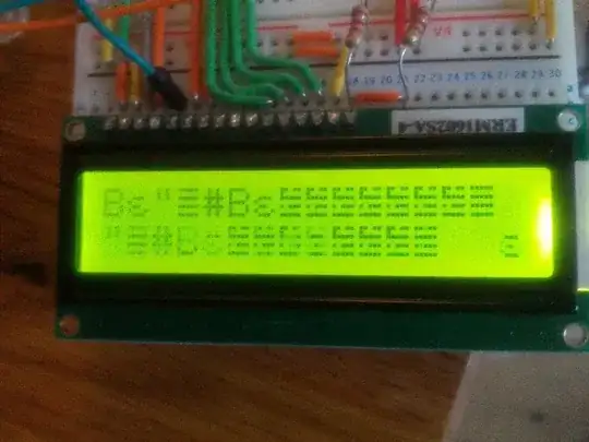
By "garbled", I mean that every time I write to it following it becoming garbled, rather than writing english characters, I get a string of characters, that I usually cannot identify in the datasheet (though some I can). This string of garbled characters tends to move left along the screen as I write new text to the LCD.

I am confident it's not the Arduino itself getting confused, as I write the same text to the Serial monitor at the same time, and it is not garbled.

I've since experimented with wiring the RW pin to an Arduino output, and Data0-3 to ground, but this doesn't help. I've powered the whole device with a 9V battery or with USB, and it doesn't help. I've replaced the battery... no change.

The only thing that seems to work is having no load plugged in to the relay, but that defeats the purpose :-)

I don't have a signal analyser or anything more sophisticated than a multimeter, a laptop and an arduino... Does anyone have any hints for helping me debug this?

LCD Summary Sheet: http://oomlout.com/LCDD/LCDD-SUMM-BC1602A.pdf

LCD Specification: http://oomlout.com/LCDD/LCDD-DATA-BC1602A.pdf

Example of garbled text: garbled text

abdullah kahraman
  • 5,930
  • 7
  • 59
  • 104
Richard Russell
  • 351
  • 2
  • 4
  • 10
  • 1
    Try adding an at least 1 uF capacitor to your power rails, that is one end of the capacitor to Vcc and other is to GND. Be careful with the direction of the capacitor if it is an electrolytic :) – abdullah kahraman Jun 19 '12 at 08:12
  • 1
    This is really bizarre. You're not driving that big relay directly, the relay box you bought actually has a tiny DIP SSR which is switching the power to the big relay, and the big relay is run off of the AC line. As such, there really should be no way for the back-emf generated by the relay actuating to get into your circuit. – Connor Wolf Jun 19 '12 at 08:49
  • This smells like a grounding/decoupling problem. Hoe much capacitance do you have across your power rails on the breadboard? – Connor Wolf Jun 19 '12 at 08:50
  • Also, how close is the relay box to the breadboarded circuit? Can you put a few feet of wire between the relay box and the rest of the circuit? That would remove the possiblity of any magnetic coupling. – Connor Wolf Jun 19 '12 at 08:51
  • Thanks for the responses. You're correct that the relay is decoupled with an SSR and various other components. I did try a diode, and later I tried a 220uF electrolytic capacitor between 5V & GND on the power rails near the LCD. Neither of these seemed to have an effect. I didn't (yet) try the two together. – Richard Russell Jun 20 '12 at 18:38
  • I also tried consciously moving the AC circuitry about a foot away from the 5V circuit, leaving only the 5V relay signal wire connecting them, but this didn't help. In my experimentation, I discovered that a small load on the relay (85W halogen lamp) doesn't seem to have much effect on the display, but if I have a large load (2000W kettle), it's more likely to cause the error. I have seen this problem with the lamp earlier, though infrequently. – Richard Russell Jun 20 '12 at 18:39
  • http://electronics.stackexchange.com/questions/153525/how-to-fix-hitachi-hd44780-16x2-lcd-garbled-display-in-4-bit-mode/153528?noredirect=1#comment311446_153528 – Manu de Hanoi Feb 15 '15 at 11:53

4 Answers4

5

Do you have a diode across your relay? If not the inductive spikes on closing/opening will likely cause problems.

When you e.g. stop the current flowing through a relay, it tries to keep it going, if there is no route of discharge it will create a large voltage (essentially it will keep rising until it finds a route).
Specifically the formula is V = L(dI/dT). This means the inductor opposes changes in current through it by developing a voltage across it proportional to the rate of change of current.

Try placing a diode across the relay, orientated to oppose normal current flow.

EDIT - checking the product page it seems it is a "ready rolled" relay in a box with peripheral components added, so it's unlikely to be the above. Even so I would try placing the diode across the power to the relay.
Also make sure your supply is well filtered as mentioned in the comments. Place a few capacitors of at least 1uF next to the ICs and LCD, and a bulk cap of >100uF somewhere (all from power to ground)

Oli Glaser
  • 54,990
  • 3
  • 76
  • 147
  • Look at the datasheet for the "Relay". The input to the relay is actually driving a tiny SSR, which switches the actual power to the relay itself. Since the input to the relay thingie is a SSR input, I don't see a diode really doing anything. – Connor Wolf Jun 20 '12 at 09:31
  • I had a look (I couldn't find it before) and I agree, it was just a "can't hurt" type of suggestion without more info. Hopefully we'll get an update soon on how it is with decoupling added. – Oli Glaser Jun 20 '12 at 10:05
  • Thanks for the response. You're correct that the relay is decoupled with an SSR and various other components. I did try the diode, and later I tried a 220uF electrolytic capacitor between 5V & GND on the power rails near the LCD. I didn't (yet) try the two together. – Richard Russell Jun 20 '12 at 18:35
  • I also tried consciously moving the AC circuitry about a foot away from the 5V circuit, leaving only the 5V relay signal wire connecting them, but this didn't help. In my experimentation, I discovered that a small load on the relay (85W halogen lamp) doesn't seem to have much effect on the display, but if I have a large load (2000W kettle), it's more likely to cause the error. I have seen this problem with the lamp earlier, though infrequently. – Richard Russell Jun 20 '12 at 18:36
  • A ceramic cap of 1uF or so would be better for transients, add one in parallel with the 220uF. Try adding another one or two >100uF cap(s) also, across +5V and GND near the relay wires. Can you show us a better picture of your setup? – Oli Glaser Jun 20 '12 at 19:33
  • Thanks - I'll go buy some assorted capacitors (1uF, 2x100uF - should I get others to experiment with?). I'll add a photo later - I don't have a wiring diagram. It's a little complex to follow as there are other circuits on different pins. – Richard Russell Jun 20 '12 at 20:09
  • Regarding choosing capacitors, how do you know which capacitance to choose? What's the goal of having multiple different capacitances between the lines? I realise that's quite an ask - is there a reference you can point me to that will help? – Richard Russell Jun 20 '12 at 20:12
  • Don't worry if you haven't got those exact values, just use something similar (e.g. 0.1uF, 2.2uF, etc) For the larger value, anything *above* 100uF. It get's a bit tricky to explain quickly, but the essentially the reason to parallel capacitors is that different types are more effective at different frequencies (e.g. ceramics are better then electrolytics at at higher frequencies) Different values and case sizes make a difference (due to the inductive properties of the case) and at high frequencies this can make a real difference (look at e.g. FPGA supply decoupling) – Oli Glaser Jun 20 '12 at 20:49
  • Here's one [reference](http://www.ti.com/lit/an/sloa069/sloa069.pdf) from TI, and a very thorough treatment of [supply decoupling](http://www.murata.com/products/catalog/pdf/c39e.pdf) from Murata. – Oli Glaser Jun 20 '12 at 20:55
1

I had the same problem with a 16x4 LCD display when the Arduino was also controlling a SainSmart opto-isolated relay board. Everything worked fine with the relay contacts unconnected. But when the relay switched an inductive load (a 24 VAC power relay), the display garbled. No amount of power isolation and filter capacitors helped.

What solved the problem was a snubber (capacitor and resistor in series) across the SainSmart relay contacts. I used a prepackaged Cornell Dubilier EMI/RFI filter for neatness, but a garden-variety 0.1 ufd capacitor in series with a 47-ohm resistor would probably work just as well.

  • may I see the circuit diagram on how you series the capacitor and resistor with the relay. THanks – Sam San Mar 02 '16 at 18:29
1

I was banging my head why my LCD is "garbled" and it turned out I haven't connect my Arduino GND to breadboard (if this is of some help to someone). Regards

bobe
  • 21
  • 1
-1

use shielded cable on the output and ground it. It solved the problem for me.