10

I recently got around to trying out buck regulators, my results weren't what I was expecting though. For one the ripple voltage seems a little high to me, It's about 800mV with no load and goes up to 4.5V with a constant 1A load. In fairness it's only short spikes that create this ripple. Here's a capture of the regulator with no load:

No load

At 1A the output voltage drops about 100mV and the voltage spikes get fairly big:

1A load

I'm using the XRP7664 in the setup given in the data-sheet but changed the output voltage to 6V (Schematic on page 1 with R1 changed to 56k). The circuit was built on a breakout board and connections made with wires. My question is this: Is this normal operating behavior for a buck regulator?


R1 changed to 56K

Schematic

s3c
  • 2,525
  • 2
  • 21
  • 31
  • I've been using this document, ["Noise Management in Portable RF Systems"](http://www.ti.com/lit/ml/slyp091/slyp091.pdf), as a resource in understanding buck regulator noise. – Atav32 Jun 18 '12 at 17:10
  • Datasheet, page 1 with R1 changed to 56k – s3c Jun 18 '12 at 17:30
  • 1
    @vicatcu Well, when it is an SMPS that at least can create the desired output voltage, then it is: `PCB layout or it didn't happen` :) – abdullah kahraman Jun 18 '12 at 17:35
  • 1
    @abdullahkahraman, It was made on a breadboard, someone just has to write an answer explaining how this is caused by the breadboard. – Kortuk Jun 18 '12 at 18:46
  • What is your load? Also what is the input voltage, and how clean is it? 4.5v is a bit high ripple for a buck converter. – Reza Hussain Jun 18 '12 at 18:50

2 Answers2

10

First of all, inductance of most of the circuit elements and loop sizes start to matter when dealing with high frequency, high \$\dfrac{dI}{dt}\$ or high \$\dfrac{dV}{dt}\$.

High \$\dfrac{dI}{dt}\$ means that current will change too much in little time, for example when current goes from 100mA to 2A in 1ns. Let's solve this:

\$\dfrac{dI}{dt}=\dfrac{(2-0.1)A }{10^{-9}s}=\dfrac{1.9A}{10^{-9}s}=1.9*10^9V\$

Now this is high. But how do I know this is high, compared to what? Cited from Wikipedia:

The effect of an inductor in a circuit is to oppose changes in current through it by developing a voltage across it proportional to the rate of change of the current.

And that voltage is:

\$v(t)=L*\dfrac{dI}{dt}=(25*10^{-9})*(1.9*10^9)=47.5V\$

That means if your current across a 25nH inductor goes to 2A from 0.1A in 1ns, then you are going to produce 47.5 volts across it, that is a lot! Since longer wire means longer inductance, it means more voltage at the same time. A 5cm wire with 5mm diameter is about 30nH. Check out this tool.

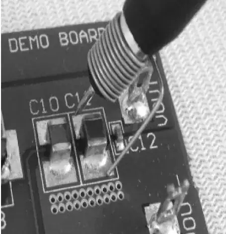
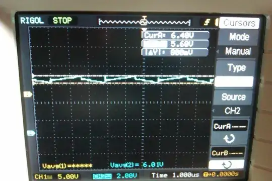
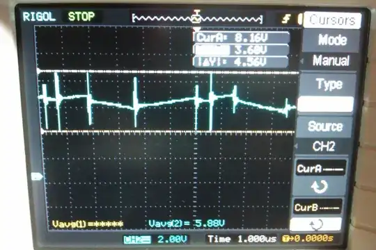
The switching transients (not ripple) that are on the pictures you have added are probably because you have breadboarded this circuit with long and thin wires, or because of your bad probing techniques, or both.

Now that you know you need to shorten and widen the traces/wires when you are dealing with SMPSs and you know why.

That in mind, here is the checklist you should obey when dealing with switch-mode power supplies:

  • Try to make a PCB with a solid ground plane. If you can't, then;
  • Keep the traces as short and wide as possible where there is high \$\dfrac{dI}{dt}\$ or high \$\dfrac{dV}{dt}\$.
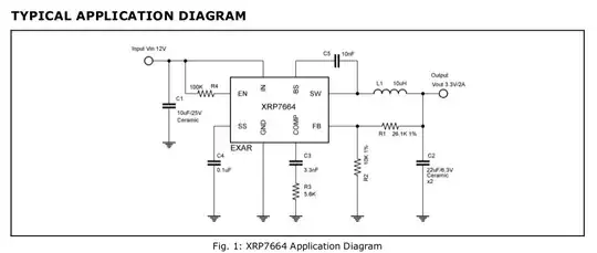
  • In your buck-converter, these include the wiring from the input capacitor ground to the IC ground and the wiring from input capacitor to the input (IN) pin of the IC.
  • When measuring the output ripple, put your scope's probe directly on the output capacitor and the probe's ground lead directly and shortly on the ground on the capacitor, as shown below:

How to measure the output ripple of an SMPS

abdullah kahraman
  • 5,930
  • 7
  • 59
  • 104
3

Above and beyond the switching spikes commented on by others, I see signs of unstable operation in the 1A waveform.

When you look at a typical buck ripple waveform, you should see a sawtooth waveform much like what your first waveform shows. The period should be stable from switching cycle to switching cycle.

Your second waveform shows wildly erratic period and frequency. This is most likely noise-related, since you've indicated that you've not implemented this buck on a PCB but on a proto board.

You should try to spin a small PCB, or see if the manufacturer has an evaluation board that you can play around with.

Adam Lawrence
  • 32,921
  • 3
  • 58
  • 110