12

I am having difficulty measuring current into an IoT device that I am making. I need to be able to gather data about power consumption over time, and about the sleep mode current. I was trying to use a shunt resistor to gather the current data, but I am running head first into a problem with Georg Ohm, and all of his laws.

In sleep mode, my device should use about 800 µA of current, my not so accurate PSU is saying that it is outputting about 2 mA, so maybe I have a bit more coding to do. However during sleep mode, at seemingly random intervals the modem will turn back on for a brief moment and transmit, (standard deep sleep modem behavior). This transmit burst can be up to about 1.5 A.

Anyway, I am having a problem using a shunt resistor because a voltage drop that allows me to see any meaningful data on sleep current, drops so much voltage during a transmit burst that my device restarts.

Could anyone recommend a way to measure current such a large current range?

Device specifications:

  • Sleep mode current: 600 µA - 3 mA
  • On current: 27-80 mA
  • Transmit burst: up to 1.5 A
  • Voltage: 2.6 V - 4.2 V
  • Charge current: 400 mA
Peter Mortensen
  • 1,676
  • 3
  • 17
  • 23
Reid
  • 2,030
  • 1
  • 21
  • 38
  • 3
    Ideally, you would piece everything together from individual measurements taken at different locations in the circuit and different times. So, there would be a shunt that leads to the 1.5A load, and a separate one that goes to the processor, etc. – user57037 Nov 17 '17 at 04:39
  • 3
    How much burden voltage can you tolerate across the shunt? – ThreePhaseEel Nov 17 '17 at 04:48
  • 1
    How about putting a x100 or x1000 opamp non-inverting amplifier on the shunt output? Measure both the shunt itself and the output of the opamp. When the opamp is not in saturation use that value for the sample. When saturated, use the direct measurement. – Dean Franks Nov 17 '17 at 05:07
  • Hi Reid. What's the value of the shunt resistance that gives you meaningful data on sleep current? What kind of current sensing circuit are you using with it? Is this current sensing setup for bench evaluation only? Or, will it be a part of every device in the field? – Nick Alexeev Nov 17 '17 at 06:35
  • What kind of speeds do you need? – pipe Nov 17 '17 at 08:13
  • The [µCurrent](https://www.eevblog.com/projects/ucurrent/) is for this kind of application, practically eliminating the effect of the [burden voltage](http://zone.ni.com/reference/en-XX/help/370384N-01/dmm/burden_voltage/) that you are experiencing. You can even use it in combination with an oscilloscope to measure the transient current (e.g. when the modem wakes up). – Peter Mortensen Nov 18 '17 at 17:53

8 Answers8

19

How much accuracy do you need? If you only need an estimate, then a series silicon diode will give you more or less logarithmic indication over a wide range of currents.

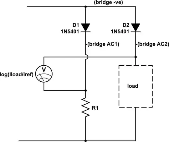
The main problem with a diode, the variation in voltage drop with temperature, can be significantly mitigated by running a second diode at the same temperature with a reference current. Two diodes within a rectifier bridge would be thermally coupled and ideal for this, I've marked the connections on the schematic, bridge +ve stays unused. As your load is very low power and the high currents are only short pulses, even two individual diodes taped together should be OK. A 1N540x for instance is good for 3 A continuous and will still have a significant forward drop at 100 µA.

It has the advantage that the load voltage changes very little, perhaps a few hundred mV between 500 µA and 1.5 A, much less than with a resistive shunt that will measure mA.

schematic

simulate this circuit – Schematic created using CircuitLab

Replacing R1 with a current sink would make the reference current more accurate, but (power supply voltage - 0.7 V)/R1 is probably adequate for most purposes. Ideally, the reference current would be in the middle of the range you want to measure best. Somewhere in the 1 to 10 mA range feels good.

The voltmeter reading will be proportional to the log of the ratio of load to reference current. The output impedance from the diodes is very low, so amplifying the difference with an opamp, perhaps to scale it or to ground-reference it, will be straightforward.

You will need to calibrate the measurement conversion at high and low currents to establish the log law, and it would be good to check it at a few points in between. Remember that calibrating at high current will heat the load diode, so you may need to use short pulses, as short as your transmit pulses, to minimise thermal drift errors.

Peter Mortensen
  • 1,676
  • 3
  • 17
  • 23
Neil_UK
  • 158,152
  • 3
  • 173
  • 387
12

An extension to Neil_UK's answer, if you need decent accuracy on sleep current but don't care about measuring high current with the same circuit, is to put a diode and resistor in parallel:

schematic

simulate this circuit – Schematic created using CircuitLab

This way, when the current is low, the voltage across the resistor will be nicely proportional, and it will be low enough that the diode is effectively off, so it doesn't shunt too much of the current away from the resistor (though check the specs on your diode).

When the current is high, the diode is conducting and limiting the voltage drop to some reasonable value. If you want to measure the current at this time as well, you can add another shunt in series, like so (idea courtesy of @dim):

schematic

simulate this circuit

Abe Karplus
  • 2,611
  • 1
  • 13
  • 19
  • 1
    You could even have two shunts: one with a ~0.1Ohm value for the high currents (without diode), and one 100ohm with the diode in parallel for the low currents. This way, you can accurately measure both ranges and the worst case total drop will be limited to ~1V. – dim Nov 18 '17 at 18:46
  • @dim Yes, though one of the shunts would no longer be ground-referenced, so for testing I'd just swap them manually. – Abe Karplus Nov 18 '17 at 20:47
  • 1
    If you put the lower-value, high-current shunt closer to ground, the error will be negligible when you measure low currents. Or use a 99.9ohm value for the other shunt to compensate. – dim Nov 19 '17 at 03:13
4

You describe this as a wide range. It really isn't.

Your maximum of 1.5A is 1875 times your minimum of 800uA. A 16-bit ADC has a range of 65535 bits. If you set a maximum limit of 5A, and allow the current to be positive or negative, that gives you a resolution of 153uA per bit. If the current doesn't change too fast, you can improve your resolution even further with oversampling - for example, 16 times oversampling would take this down to 38uA per bit. So there's no problems doing the measurement.

Your problem is simply the voltage drop on the shunt resistor. Mr Ohm has the answer there - make your shunt resistor smaller! You can easily buy a 0.1 ohm resistor, and even 0.01 ohm. (Google "0R1" or "0R01", which are the standard ways of denoting fractions of an ohm.)

The problem after that is how to measure the voltage across the shunt. You'll need a differential amplifier with a very high input impedance, so that you can measure the voltage without affecting it. You then want to put some gain on it, so you can drive the ADC with a suitable voltage.

Low voltages mean more noise problems, so pay attention to track routing and all the other best-practise layout stuff. You'll also need to pay proper attention to stable power supplies and references. Switch-mode regulators are not your friend here. Even a linear regulator after a switch-mode doesn't necessarily have enough PSRR to properly kill off the ripple.

The gain stages will inevitably have some DC offset on them. You'll need to include a self-calibration step where you measure the ADC reading with no current and then subtract that zero reading when you're actually doing current measurements. You could do this automatically on startup (many meters "tick" as they start up, and it's because they're switching between onboard references to do that auto-calibration) or you could do it once and then store the results in NVM.

Bear in mind that this is the short answer! I hope this gives you some pointers for how to tackle the problem.

Graham
  • 6,020
  • 13
  • 20
  • 2
    Thank you for the response, however I have tried reading in the current with a 16bit ADC - Found on the NI myDAQ. However the noise is just too high, if its off by just a couple of bits I get radically different battery life readings. – Reid Nov 17 '17 at 18:19
  • @Reid Yep - like I said, noise really will be a thing here! The analogue side of it really will need to be done on a proper PCB with proper balanced tracks and a decent instrumentation amplifier (or similar). Once your levels are up to solid volts, the myDAQ might be good enough. You may need a better ADC - don't know - but without a low-noise analogue side you're always going to be screwed. – Graham Nov 17 '17 at 18:25
3

I know it's an old question, but the information might still be useful.

You might want to check out some of the design concepts of the uCurrent by Dave Jones over at EEVBlog. While it does not have auto ranging it does cover the lower level measurements; Also some of the mods out there reduce number of ranges while still remaining fairly accurate.

At a bare minimum I would break the measurements up into below 1A(actually below 400mA) and above 1A(aka 1.5A during transmit) ranges.

With out more information(which I admit may not be possible at this far remove of the original question) it is hard to give specifics, but I'll see what I can do.

Unless your using a monolithic mcu/transceiver device(nrf5x, STBlue, etc) I would treat the radio supply path the same way one would would route digital current paths to avoid affecting your analog current. If you are using a high power monolithic device, the only real solution I see is to use a very small sense resistor combined with a current sense amplifier/module that has a very wide input input range. I know ADI has couple(as a matter of fact I was just looking at current sense amplifiers/modules yesterday) that may work. And if I had to guess, TI also has devices that would work.

Another source of information would be the blog of Jean-Claude Wippler over at JEELabs. Over the years(It looks like about 10+) he has done more than one experiment on board current draw while in search of longer battery life. While it may not be directly on point, it may give the OP ideas on which direction to go. This is the latest article I see on the subject matter. To see the long list and history of his work, I used the simple google search of

site:jeelabs.org current measurement

I just discovered the CurrentRanger, which takes the uCurrent concept(low burden current measurements) to a whole new level. Auto ranging, serial output and a optional OLED display are just a couple of the new features. The schematic and firmware are available and Felix goes into a fair amount of detail on the design.

Edit: better detail of what I was thinking by linking those pages.

Second Edit: Add the CurrentRanger. One of the complaints in comments was that the uCurrent was not auto ranging.

GB - AE7OO
  • 1,043
  • 7
  • 19
2

I have had the dynamic range issue when testing automotive switch-mode voltage droppers. For expected input currents of up to 5 amperes I used a 100 milliohm shunt.

When testing if the no load current drawn from 24 V was less than 7 mA I used a 10 Ω shunt with a 10 A Schottky diode across it. The shunt combination stayed in my test jig. I switched my DVM between the two shunts with a DPDT slide switch.

This was in 1995 and numbers were not big. These days you could electronically switch to monitor the shunt voltages. You could have more than two series connected shunts if needed. The key to this is to bypass the high resistance low current shunt with a diode.

Peter Mortensen
  • 1,676
  • 3
  • 17
  • 23
Autistic
  • 14,235
  • 2
  • 27
  • 65
2

One trick I have used in the past is to put the sense resistor inside the feedback loop of an op-amp. This allows the supply voltage to the device under test to be held fairly constant while allowing a higher voltage to be developed on the shunt resistor.

In my case I combined this with several instrumentation amplifiers and ADCs running in parallel to get a wider dynamic range.

I describe the system I built in chapter 5 of my PHD thesis. My system won't be directly applicable to your application, but it may give some ideas of the challenges to be faced with a system like this.

Some time after I developed my DIY system I discovered that Agilent (now Keysight) had developed a similar system. Not cheap though.

Peter Mortensen
  • 1,676
  • 3
  • 17
  • 23
Peter Green
  • 21,158
  • 1
  • 38
  • 76
  • Yes, that can work. It's also a standard way of putting a current limit on the output, so that short circuits don't blow your chip. The downside though is that this is not exactly the output current - you also need to consider the current through the feedback resistors. At 1.5A that's probably not such a big deal, but it could be significant at a few tens of uA. – Graham Nov 17 '17 at 14:52
  • In my design there were no feedback resistors as such. Still input bias currents both in the power op-amp and the instrumentation amps are a consideration. – Peter Green Nov 17 '17 at 15:05
1

As an alternative approach, you can use a small shunt that fits the 1.5 A range and have two separate gain circuits fed to two different ADCs. By software you can then choose which one to use based on their reading. With higher current you'll have the higher gain ADC saturated, and you'll know that you have to use the other one.

clabacchio
  • 13,481
  • 4
  • 40
  • 80
1

The problem is all about signal integrity with EMI reduction.

1.5A/0.75mA means a 66 dB SNR and accuracy on the ADC.

Background noise must be shielded, suppressed, filtered with excellent CMRR and averaged in order to achieve this with a good 16 bit ADC.

If you don’t have this resolution then you can have two different inputs with one having 40dB higher gain. The shunt power and allowable load regulation error voltage limits the shunt resistance and typically 75 mV max is chosen. An IC current sensor with gain may be an Moro emend.

How to achieve this requires experience. With <-90 dB resolution and a design target of 80 dB SNR hopefully, you can achieve 70 dB SNR.

Tony Stewart EE75
  • 1
  • 3
  • 54
  • 182