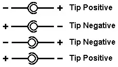
Open up the device trace some circuit board traces and look for clues. For instance: polarity of electrolytic capacitors, or wiring of three-terminal voltage regulators, or the direction of diodes (but you have to understand the circuit for that one: sometimes diodes are reverse biased on purpose). If you see a diode which is connected squarely between the power rails, then it is reverse biased. The stripe end (cathode) of the diode is then on the positive rail. It provides a bypass path for incorrect polarity.
If there is any integrated circuit which is clearly marked, and you can find the data sheet, then you can determine which of its pins is ground. Then you can check for continuity between the tip or ring of the power connector and that pin, either with your multimeter, or by tracing the board and wiring.
There may be additional clues inside the device, like silk-screen markings on the circuit board such as VCC, GND, or other polarity indications. The circuit board might have an obvious ground plane, whose continuity can be traced to the connector.

