2

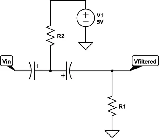
I'm quite new to electronics and I'm trying to make a high pass filter to get rid of some DC component of a signal. For that, I thought of using a capacitor along with a resistor in the usual HPF configuration (values are generic):

schematic

simulate this circuit – Schematic created using CircuitLab

However, since my signal is positive and negative, as far as I understand I can't use an electrolytic capacitor since they are polarised. To make up for that, I thought of the following configuration (it is quite simple so if it works I guess it may be quite standard), but since I haven't designed many circuits I have no idea if it works or not:

schematic

simulate this circuit

Is this any good? Thanks in advance!

popeye
  • 103
  • 4

3 Answers3

3

A couple notes:

  • A high-pass filter removes or changes the DC level of a signal.
  • The polarity of the DC-blocking capacitor cares only about the DC level of both sides, not the alternating high-frequency signal.

So if you know whether the offset voltage will be positive or negative, you can use the simple circuit.

If the offset can vary higher or lower than the desired output offset, you can arrange two high-pass filter stages where you know the direction of each. For example, if the input offset can vary around 0V but never be more than +5V:

schematic

simulate this circuit – Schematic created using CircuitLab

Ben Voigt
  • 2,743
  • 1
  • 22
  • 34
  • This looks much better and I understand it too. Thanks a lot! Also, are 100uF caps and 10kOhm resistors ok? The signal is just a 10kHz sine with an offset – popeye Nov 10 '17 at 19:45
  • You don't need the +5V offset... – Voltage Spike Nov 10 '17 at 22:14
  • @laptop2d: It's there for a reason. Yes, leakage current *should* eventually build up an appropriate offset on the node between the capacitors, but in a completely uncontrolled way and violating the maximum ratings in the process. Or, you can simply weakly bias that node to a power rail you already have in your system, which makes everything controlled and predictable. Floating nodes are bad. – Ben Voigt Nov 10 '17 at 22:42
  • So what would you suggest R2 be? You don't want to bleed out AC. – Voltage Spike Nov 10 '17 at 23:16
  • @laptop2d: As long as it is larger than R1 it won't have much effect on the cut-off frequency. – Ben Voigt Nov 12 '17 at 16:30
  • Or you could let the parallel parasitic resistance in the capacitor do its job and leave out R2. – Voltage Spike Nov 13 '17 at 18:00
  • @laptop2d: Like I said, if you are confident that the leakage there is fast enough for your needs and faster than the leakage from the center node (parasitic PCB conductance, for example) and that the capacitor manufacturer will never change his process to reduce leakage, then yes you can let the middle node float. I don't consider that to be a good idea. – Ben Voigt Nov 13 '17 at 18:20
0

Do this instead:

enter image description here

The reason for this is that electrolytic capacitors, which are used when large capacitance values are needed, require a voltage with correct polarity for their operation. These capacitors are made from aluminum foil that is oxidized on one side by an electrolytic process. The foil is submerged in some liquid or paste (the electrolyte) and current is passed through the liquid to the metal, forming the oxide layer that provides the insulation between the two "plates" (the aluminum foil and the electrolyte) of the capacitor. Applying a voltage with reversed polarity will damage (short circuit) the oxide layer and the capacitor will eventually become non-functional or even explode. Since we are going to use the capacitor with an ac voltage, we have to use the little trick, shown in the schematic above, of connecting two electrolytic capacitors with the same capacitance C in series, either with the two + terminals or with the two - terminals connected together as shown above.

Source: ECE Colorado

Voltage Spike
  • 75,799
  • 36
  • 80
  • 208
  • So now you always have one capacitor with incorrect polarity... – Ben Voigt Nov 10 '17 at 19:41
  • Ok, this looks rather similar to the other suggestion but without the voltage in the middle. Is it ok to not put it? Why? – popeye Nov 10 '17 at 19:45
  • No, its not, because of the dielectric polarization you can use them in this way without problems. Related: https://electronics.stackexchange.com/questions/21928/can-you-make-a-non-polar-electrolytic-capacitor-out-of-two-regular-electrolytic – Voltage Spike Nov 10 '17 at 19:45
  • See the link in comments for questions on why this is acceptable – Voltage Spike Nov 10 '17 at 19:46
0

If the source has DC component, and the purpose of the cap is to remove that relative to 0V then a single polarized e-cap will work fine with the +() cap terminal in series towards the (+) source.

Get a 100uF @ 50V is only $0.33 or get a non-polarized cap for twice the cost. Two series caps also raises the HPF cutoff x2.

@Laptop2d 's cap model is exactly what is inside a non-polarized 23 uF cap, I expect the values shift widely with DC bias.

Tony Stewart EE75
  • 1
  • 3
  • 54
  • 182
  • So even if my signal goes lower than 0V during part of the cycle (say 3V amplitude sine + 1V DC offset), I can still use a single electrolytic capacitor to remove the DC component provided I aim the + side of the capacitor towards the source if the offset is higher than 0 and away if its less? – popeye Nov 10 '17 at 19:59
  • Generally e-caps can withstand 10% of their rated voltage in reverse without significant leakage, so in that case choose a Cap rated for >20V. How did you get so much offset if your source signal bipolar ? duty cycle? – Tony Stewart EE75 Nov 10 '17 at 20:21
  • @GastonMaffei: Yes, if you know you have a +1V DC offset you can use the single electrolytic capacitor. That's what I meant when I wrote "if you know whether the offset voltage will be positive or negative, you can use the simple circuit". The reason is that when your input peaks negative at -2V, the output is -3V, and the capacitor polarity is still correct). – Ben Voigt Nov 10 '17 at 22:47
  • TonyStewart.EEsince'75 (wouldn't let me notify you): It's the output of a cheap function generator that I purchased for around 10-15 dollars, and I just wanted it without DC component. @BenVoigt Oh! I understand what you mean now. I thought that would be a no-go since, connected before a voltage divider, current will flow on the other direction. But I guess it's not about current flow direction, and merely about polarity, right? Thanks a lot – popeye Nov 12 '17 at 17:28