2

I am creating a 16 by 16 LED Matrix using 74hc595 Shift Registers to address the columns and using 4017 Decade Counters to control the row. I am using the 4017's in connection with a transistor to sink the current from the LED's. I understand how to use one 4017 to sink the current but I am trying to cascade another 4017 so I can count until 20 using outputs. I have an arduino providing the clock signal and have tied ENABLE output to ground, and can control CLOCK and RESET

An explanation of why a supposed solution works would also be great, as I would love to understand how my matrix works from the inside out.
2 Answers2

3

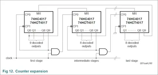
Actually the linked HC4017 data sheet explains how to expand the counter. Look at page 15. But you only get 17 stages out of 2 counters, and additional 8 stages for each additional one.

PetPaulsen
  • 2,335
  • 4
  • 22
  • 34
hli
  • 2,336
  • 15
  • 17
  • Neither you nor the OP provides a link to a datasheet. Are you referring to the [link](http://www.nxp.com/documents/data_sheet/74HC_HCT4017.pdf) that stevenvh provides in [his answer](http://electronics.stackexchange.com/a/33667/4950)? If so please include the link in your answer too. Otherwise it is realy confusing (at least it was for me). – PetPaulsen Jun 11 '12 at 12:46
  • @PetPaulsen - I agree, you can't have too many links! Actually the reference was to a link in my now deleted answer, but I repeated it in my new one. – stevenvh Jun 11 '12 at 12:52
  • @stevenvh - Ok, now that I am sure hli is referring to the mentioned datasheet, I have edited the answer. – PetPaulsen Jun 11 '12 at 13:11
3

My other answer was wrong: I erroneously presumed you would use all outputs, and then it can't be done with the 74HC4017.

hli rightly remarked that the datasheet shows how you can cascade them:

enter image description here

(So upvote his answer, not mine. Unless you agree with the following. :-))

The 17 lines remaining for two devices are sufficient for your 16 \$\times\$ 16 display.

I still would use two 74HC595s, and cascade them after the column '595s. I mentioned one reason in my other answer: the '595 is cheaper, and you won't need the AND gate.
Another reason is that the shown circuit has no means to synchronize. If you lost count one way or another (ever heard of bugs?) your display will show the wrong data and you wouldn't know. You can fix that by intercepting one of the MR inputs. Costs you an extra I/O, and complicates your driver. For the '595 you don't need a new driver, you already have one for the columns. Just 2 more bytes to shift through.

stevenvh
  • 145,145
  • 21
  • 455
  • 667
  • I've reverse engineered a couple of matrixes, and i would like to say, that driving rows via 595 is asking for trouple - you easily can turn all line or all display by making a mistake in a code, and pufff - lots of smoke. – miceuz Jun 11 '12 at 16:51
  • What i would suggest is to use 74hc138D to drive rows - this way the solution is much more foolproof, but uses up MCU pins of course. – miceuz Jun 11 '12 at 16:54
  • @miceuz - One '138 needs only 3 lines. So for 16 lines I guess that for safety you use a couple of gates to prevent one from being active when the other is. – stevenvh Jun 11 '12 at 16:58
  • The '138 includes both active-high and active-low enable pins (three in total, iirc). So one could use four wires to select a row, with an optional fifth serving as a global enable. My recommendation would probably be to use a 74HC138 and a four-bit counter, driven by a "nudgeable" timer circuit (whose output would match its input when the input frequency was in range, but which would free-run if the input goes out of range). – supercat Jun 11 '12 at 18:16