0

I have a little BLE device that can drive an LED at variable brightness (according to a programmable 0-255 byte value). This works, but has the major caveat that it can only source 5 mA, whereas many LEDs are spec'd to run at 20 mA nominal. The result is that it can only drive the efficient tiny SMD chip LEDs, and not most discrete LEDs.

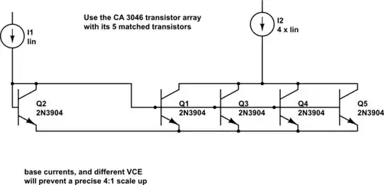
So I'm looking to make a little current amplifying circuit to take the 0-5 mA and amplify it to the range of 0-20 mA. What approach would be the best to go about doing this? Any pointers are greatly appreciated.

Jakub Rakus
  • 2,225
  • 5
  • 18
  • 26
tansvaal
  • 3
  • 1
  • What's the voltage of the IO pin, and what other voltages do you have in the system? – pipe Oct 23 '17 at 19:00
  • 1
    You have to show the actual schematic of what you're doing. I **doubt** that you have 0 - 5 mA coming out of the BLE device but that you're actually using PWM to dim the LED. In that case you do not need a current amplifier circuit, what you need is simply a MOSFET that is controlled by the PWM signal. That MOSFET then drives the LEDs. There are plenty of questions to be found on that subject on this site. Also, **specify** which BLE device you're using. All in all this question is too vague to answer properly. – Bimpelrekkie Oct 23 '17 at 19:07
  • The device in question is an RFduino RFD22301. The way it's set up to drive LEDs is via the GPIO lines, so that does sound like PWM. The device specs say that it can source at most 5ma per GPIO line, and can drive at most three at 5ma at the same time. General Purpose I/O (GPIO) input high voltage 2.1VDC. Output high drive current 5ma. Spec sheet: [link](http://www.rfdigital.com/wp-content/uploads/2015/08/RFD22301.Data.Sheet.08.20.15_4.36PM.pdf) – tansvaal Oct 23 '17 at 19:22
  • So are you directly hooking the LED between the GPIO pin and ground, currently? – jonk Oct 23 '17 at 19:30
  • Yes, currently the LEDs connect to GPIOn (+) to common GND. – tansvaal Oct 23 '17 at 19:34
  • Are you supplying 3.0 V or 3.3 V or ? What voltage are you using? Also, what is its current compliance? (Probably fine, but I need to ask.) And finally, do you know what voltage is required for your LEDs when they are operating at 20 mA? – jonk Oct 23 '17 at 19:41
  • 1
    Before you build the booster circuit with brighter leds, don't connect the GPIO directly to led and the led to ground. It will drive all the GPIO output. You should always put a resistor between the led and the ground, or between the GPIO and the led, every two solutions does the same. – mguima Oct 23 '17 at 19:46
  • For the RFduino board, the Vcc I'm using is 3.0 V (from a button cell battery). The LEDs I'm trying to drive want 2.8 V @ 20ma (a Kingbright EALP05RDEWA1). – tansvaal Oct 23 '17 at 20:01

2 Answers2

0

You need add this to your circuit, see picture below. You can power this addition with 3V (instead of 5V as show in picture), maybe you'll have to adjust the R2 value.

You can learn more about it in the following link: https://learn.sparkfun.com/tutorials/transistors/applications-i-switches

There's an animated GIF at this page that is very good to help you understand the concept.

enter image description here

mguima
  • 1,425
  • 11
  • 20
  • Thx, but that looks like an LED switch circuit, not a current booster circuit. Or am I overlooking something? – tansvaal Oct 23 '17 at 20:21
  • 1
    @tansvaal, the current to drive the LED comes from the +5 V supply, not the control GPIO. So in that sense it is a current amplifier. – The Photon Oct 23 '17 at 20:26
  • If the current comes from the +5 V supply, then how to use the PWM signal to control the current from 0-20ma? – tansvaal Oct 23 '17 at 20:31
  • So if I connect the GPIO PWM signal to the "CONTROL" gate of Q1, then by varying the PWM signal it will have the effect of running the LED from 0 - 100% brightness (with the additional current provided by the +5 V supply going through the limiting resistor). Is that essentially correct?. – tansvaal Oct 23 '17 at 20:40
  • Yes, although the scale is not linear, i.e. 50% PWM is not 50% brightness. This is not usually important. – BeB00 Oct 23 '17 at 20:52
  • Q1 is a transistor, and its central terminal is called "base"; we never use the word "gate" to refer to a BJT (Bipolar Junction Transistor, the most common type of transistor) terminal, because the transistor will get sad and would malfunction ;-) The 'control' in the picture is the name given to the GPIO, because GPIO controls the transistor, and so controls the led. With a circuit like this, you could control even a very powerful led, of a few hundred mA. – mguima Oct 23 '17 at 21:19
  • In this proposed configuration, the 5V supply (it's 5V in picture but can be 3V, maybe it will be necessary reduce the value of resistor to about 68 ohm) will supply all the current that the led + resistor needs; when PWM pulse is high, the led is on; when PWM is low, the led is off. But if you use the same coin cell to supply current to the transistor, this will drain more power from the cell than just the 5mA outsourced from the GPIO. – mguima Oct 23 '17 at 21:29
  • Any recommendations as to transistor to use for Q1? – tansvaal Oct 23 '17 at 23:02
  • Almost any NPN transistor will fit... 2N2222, BC547, BC548... Use the first transitor that you can put your hands on. The current gain that you need is so low that even a 13001 that you can scavenger from a dead CFL lamp can get the job. Good luck! – mguima Oct 23 '17 at 23:08
  • And lastly, does the placement of Q1 matter? Currently Q1 is placed between LED1 and GND, but if Q1 is moved to between R2 and LED1, the circuit should work identically, correct? – tansvaal Oct 24 '17 at 04:05
  • The placement of the transistor matters. I suggest you read the following link and you'll find excellent answers that are better than anything that I could write (really I learned reading this; I always _tought_ that one way was better than another, but I couldn't explain all the reasons; now I know much more about this): [https://electronics.stackexchange.com/questions/151326/bjt-driving-an-led-above-or-below](https://electronics.stackexchange.com/questions/151326/bjt-driving-an-led-above-or-below) – mguima Oct 24 '17 at 12:50
  • After reading the [page](https://electronics.stackexchange.com/questions/151326/bjt-driving-an-led-above-or-below), I have more reasons to suggest that in your case the left solution (the common emitter, with the arrow transistor's terminal connected directly to ground) is far better, because you're dealing with PWM (fast transitions), and because your HI logic level is low voltage (only 3V). – mguima Oct 24 '17 at 12:58
  • I was wanting to apply this circuit to drive a common-cathode RGB LED, so I was going to just move the placement of Q1 to between R2 and LED1. – tansvaal Oct 24 '17 at 15:05
  • Really, a common catode RGB led is a good reason for adopting the second option; note that there must be three different control signals (one for each colour), and also three transistors, each one with its emiter connected to a resistor, and each resistor conected to one of the three led's anodes. Note that to make a correct balance of the colors (if the three channels are in their maximums the colour should be white) the resistors to be used may or may not have the same value (you'll have to try it for yourself, adjust differs for each RGB led model). Good luck! – mguima Oct 24 '17 at 15:29
0

schematic

simulate this circuit – Schematic created using CircuitLab

analogsystemsrf
  • 33,703
  • 2
  • 18
  • 46