7

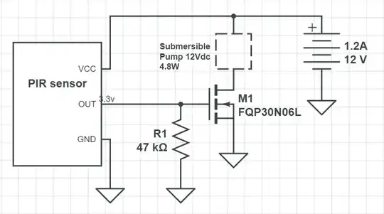
I've built this circuit to control a submersible pump with a PIR sensor.

Pump Circuit

The circuit works as expected (the PIR sensor activates the mosfet, turning the pump on) but only after about 30 seconds from when power is initially turned on. Before that the circuit behaves almost randomly - as soon as the power is turned on the pump immediately runs for 10 or so seconds then turns on and off a few times randomly, not in correspondence to what the sensor would be outputting.

My only slightly educated feeling is that this has something to do with transients or the lack of diodes in the circuit so any insight into how to improve this would be appreciated.

Link to PIR sensor here

Edit: I've added a flyback diode in parallel with the pump and whilst this was obviously required, it didn't change the strange start up behaviour.

Seano
  • 163
  • 1
  • 2
  • 12
  • 3
    Could just be the PIR sensor's own delays in figuring itself out after it is powered up. You could test this idea by hooking it up to a microcontroller and then record the first 10 seconds of data coming out of it (or else use an oscilloscope.) I don't think there's anything else in your circuit with 10 s timings present. – jonk Oct 21 '17 at 05:11
  • If the sensor has a 'boot up' phase or something when its first supplied power like I believe you are alluding to, would it make sense that the sensor would be unresponsive to movement and therefore give no/delayed signals until this phase is complete? Unfortunately I don't have a microcontroller or oscilloscope at my disposal. Thanks for your comment @jonk – Seano Oct 21 '17 at 05:26
  • 1
    No telling, for sure. The datasheet you linked is quite poor. I've seen PIR datasheets that actually say that their output isn't any good for about the time you indicated. Just recently, in fact. During that time the output (on that device) was said to be unreliable. Which I'd take to mean that it may have some, but unpredictable, responses to external stimuli. The OP in that case was looking for a way to inhibit the attached circuit. – jonk Oct 21 '17 at 05:32
  • 1
    I see another problem in your circuit. You lack a freewheeling diode in parallel to your pump to protect the MOSFET from voltage spikes when the pump is turned OFF (unless the pump is specifically designed to include such a diode or other protection circuits that avoid that inductive kick). – LorenzoDonati4Ukraine-OnStrike Oct 21 '17 at 07:10
  • BTW, just to isolate problems, you could substitute your pump with a simple LED+resistor and see if the behavior is the same (LED ON/OFF randomly). So that you could exclude the pump turning ON/OFF is not generating some EMI that creates problem with the PIR module internal circuit. – LorenzoDonati4Ukraine-OnStrike Oct 21 '17 at 07:13
  • Another problem I see is that when the pump turns ON it could generate a current spike (inrush current of the motor) on the power rail which could bring the voltage on that rail below the minimum supply voltage needed by the PIR module (5V). Adding decoupling caps across the PIR supply pins could be necessary. Moreover, did you check if the wires from the supply to the pump are sufficiently thick? – LorenzoDonati4Ukraine-OnStrike Oct 21 '17 at 07:23
  • Adding some photos of your real setup could help us a lot in diagnosing a possible problem. – LorenzoDonati4Ukraine-OnStrike Oct 21 '17 at 07:25
  • Are you using FQP30N06L? – winny Oct 21 '17 at 08:21
  • Would any 1N400x diode suffice for this application? The PCB of the sensor has 4 capacitors on it...would these be for the purpose you mention? Also, I'm using an old wallwart I had lying around for power supply @LorenzoDonati Thanks for your help – Seano Oct 22 '17 at 01:26
  • Yes I am, why's that? @winny – Seano Oct 22 '17 at 01:26
  • 1
    Not *any* 1N400x: that *x* represents the maximum reverse voltage. Choose 1N4007 to be on the safe side (it can resist up to 1000V). As for the current, you should be safe, if the data of your pump is correct: at 12V 4.8W corresponds to less than 0.5A continuous. When you switch the pump off, that current is dumped into the diode (initially, then it will decay off as the energy in the pump windings is dissipated). The 1N4007 is rated for 1A continuous (and much more for non-repetitive pulses), so it is OK. – LorenzoDonati4Ukraine-OnStrike Oct 22 '17 at 07:54
  • "The PCB of the sensor has 4 capacitors on it...would these be for the purpose you mention?" How could we tell?!? We are not psychic! We have no schematic of that module nor a photo of your setup. I don't like playing a guessing game without all the relevant information. This is becoming increasingly frustrating. I repeat: *post more detailed information if you want help*! – LorenzoDonati4Ukraine-OnStrike Oct 22 '17 at 07:57
  • In case the schematic editor defaulted to that one and you where using something different. 3.3 V should be enough Vgs to support your 400 mA of current for this transistor in particular. – winny Oct 22 '17 at 08:23
  • My apologies for the vagueness of some of my statements. I'm clearly a newbie here. I appreciate the help none the less @LorenzoDonati – Seano Oct 24 '17 at 10:58
  • 1
    Show us the pinout for the PIR sensor as built, not as described in the datasheet. Pinouts and grounds are the first things I check when something starts acting funny. Crank your two potentiometers on the back fully counterclockwise, too, and see if things start up a little better in this case. – Jason_L_Bens Dec 12 '17 at 16:32

1 Answers1

4

This isn't strange behavior... it's the expected behavior! The pump is turning on and off exactly in correspondence with what the PIR sensor is outputting.

The 'strange' behavior you're seeing is totally normal and to be expected for any Passive InfraRed sensor. It's an unavoidable artifact of how they actually work.

PIR motion sensors are ultimately differential amplifiers for infrared radiation. This is out of necessity. If one were to make a motion detector that triggered simply on the amount of infrared radiation impinging on a single pyroelectric detector, it wouldn't even really be a motion detector. It would simply be a 'change in average temperature within a certain field of view' detector. It would trigger every time the sun rose and set, and many times throughout the day (and night) from the progression of the sun and moon and how much light totally motionless things were reflecting at it. And motion wouldn't necessarily change the average temperature.

So PIR sensors' pyroelectric detectors are actually split into two detection areas, and usually the optics/fresnel lens is shaped so each 'half' sees a different half of the field of view. It's not a literal split screen however, but rather the split is done in an interleaved way by the optics. A 180° field of view might be divided into, say, 5 degree slices that alternate between the two sensors.

Now that we have two detectors, we can put them up to an op amp in a differential arrangement... and suddenly we have something much more useful. We have a differential amplifier, but for infrared energy being received. Things like the temperature, the sun rising and moving, that's all common mode 'noise'. It's stuff that will be common to both sensors, and so those signals cancel each other out. However, any motion against the background will alter the radiation received by each sensor unequally, and gets amplified and detected.

My point is that your PIR sensor is really just a differential amplifier and you need to treat it as such. So you have to keep in mind that your PIR sensor has a settling time. When you turn it on, this is subjecting it to a massive step-change on the inputs, and its output is going to oscillate for a time as a result. And this is a very slow amplifier, as it is operating time scales similar to humans. It generally takes 30-60 seconds for a PIR sensor to settle, and for the output to stabilize. The logic circuitry is ready to work in microseconds, so the result is the output going high and low erratically.

Another way to think about this is that the sensor needs time to 'get used to' what it is seeing before it can actually tell what is and isn't moving. However, this implies some sort of snap shotting or processing, when in reality, it is simply settling time.

This will happen to a lesser degree when motion is detected as well, but this is generally a much smaller change and so the oscillation peters out more quickly. It sounds like there is probably some sort of one-shot retriggering window logic (as is standard on these motion detectors), which is why the pump turns on for seconds, then will be off for seconds before turning on (semi-randomly) for another few second window.... Remember, any sort of transients that might be caused by a lack of diodes somewhere would be on nanoseconds to microseconds, maybe even milliseconds for some nasty inductive stuff. No transient is going to kick that MOSFET on for 10 straight seconds. The mosfet is simply doing what the output of the PIR sensor is telling it to. Unfortunately, that happens to be garbage (at least at first).

Now, how you actually solve this is really up to you and your specific situation. The easiest way is acceptance. Accept that the pump will turn on randomly when you power up this detector, but be comfortable in the understanding of why it is happening and that it isn't a big deal. Unless it is a big deal (like you really need the pump to not do that).

If it is a big deal, you'll have to forgo driving a mosfet's gate with the PIR sensor's output directly. There is probably a more elegant way to do this, but off the top of my head, just make a simple 555 delay circuit that will go high after the circuit has been turned on for 60 seconds or so. Then feed the delay circuit's output as well as the output of the PIR sensor into a logical AND gate, and drive the mosfet from the gate's output. This also buffers the PIR sensor's output, which may not be well-suited to driving a mosfet gate to begin with.

Or you could have the delay circuit control a relay that switched on the pump's power rail, this would allow you to drive the mosfet directly from the PIR sensor. You just make sure the pump's power doesn't click on until some 60 seconds after the PIR's power supply has been turned on.

Anyway, lots of options.

Oh, and while this is definitely NOT causing any of the behavior you're seeing, that pump motor is, well, a motor, and every motor is a BFI (big f***ing inductor) in disguise. BFIs that get switched on and off should always have a flyback diode connected in antiparallel. In other words, in reverse across your pump. It doesn't need to be big, but it should be either very fast, or be able to withstand a high voltage, or both. Using either a 1N4007 (slow but tolerates 1000V no problem) or an 1N5819 (fast enough that the spike never has a chance to reach more than a few volts), whichever is easier, is sufficient. Or, ideally, use a UF4007, which is the ultrafast variant of the 1N4007.

Without it, your MOSFET might explode a little.
metacollin
  • 27,884
  • 4
  • 64
  • 119