I have an older car with a known issue with the window switches: they carry all the motor current, and after a while the contacts suffer carbon buildup presumably from flyback arcing. Commonly, owners will add relays (one for each direction of each window) to spare the switches, but wouldn't it be simpler to add flyback diodes?
If so – since the motors can be driven in either direction, so a regular diode can't be added at the motor – is it better to use two regular diodes at the switch (addressing the flyback arcing where it's occurring), or two Zener diodes (or similar?) at the motor? And in each case, what would be an appropriate diode choice? (The circuit is ~13V, protected by a 30A fuse, and the resistance measured at the switch connector is 1.8Ω for driver side and 2.4Ω for passenger side, for a calculated 7.2A and 5.4A respectively.)
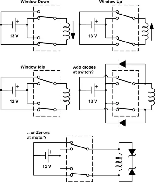
simulate this circuit – Schematic created using CircuitLab
I have found references to adding flyback diodes in this application, but only to the switching coil of the added relays (which I know some relays even have built in), not the actual window motors.
Thanks in advance for any and all answers!

