7

I have a two digit 7-segment LED display which is driven multiplexed by a microcontroller. PORTA is for the anodes. In my code I shift a 1 through PORTA. On PORTB I say which segment should light by setting it to 0. My problem is that the display isn't very bright although I don't have any resistors connected infront of the 7-segment. How can I extend this circuit to get a brighter display? Maybe with transistors or MOSFETs? I've also attached a simplyfied schematics of my circuit.

Thanks for the help in advance. enter image description here


Solution: 4 NPN transistors. enter image description here

arminb
  • 1,622
  • 4
  • 21
  • 34
  • possible duplicate of [How can I effectively drive multiple LEDs with multiplexing?](http://electronics.stackexchange.com/questions/32890/how-can-i-effectively-drive-multiple-leds-with-multiplexing) – stevenvh Jun 08 '12 at 07:48
  • Very good. FWIW technically R5-R8 are not needed. BUT they are a good idea if the driven lines are ever going to be overloaded or shorted low. BUT R1 - R4 are very necessary. – Russell McMahon Jun 10 '12 at 18:11
  • 2
    No, not good! You told us this is a common anode display, right? Then you're connecting the emitters to the cathodes, that should be the anodes. Cathodes should go to port A. Also, note that you use the transistors in common collector, and then the emitters can't go higher than Vcc - 0.7V. Your schematic says +5V, so maybe not a problem, but you may have to recalculate the resistors. For a controller running at 2.7V this wouldn't work. – stevenvh Jun 10 '12 at 18:41
  • @stevenvh thank you for the hint. I swapped PORTA and PORTB in the schematics. In my circuit I did everything fine. I corrected the schematics. About the common collector thing: I get a nice brightness though, thanks anyway for that too :) – arminb Jun 11 '12 at 00:33
  • Any reason why you did it this way, the common collector I mean? With PNPs in common emitter you can drive LED strings at a higher voltage than 5V, while here you can't even get 5V. – stevenvh Jun 11 '12 at 04:58

3 Answers3

5
  1. You definitely have to use series resistors!
  2. Don't use the 74HC244 others suggested. Read the datasheet, they can only source and sink 6mA, not 20mA.

You have a common anode 4\$\times\$4 matrix, so for a 20mA display the anode driver has to supply 80mA if all LEDs are on. The most simple solution is to use 4 PNP transistors which you drive via a base resistor from your microcontroller. A low level will activate a column. The BC327 has an \$H_{FE}\$ of 100 minimum, so a 2mA base current will be enough to switch it on. Then your base resistor is 2.2k\$\Omega\$.

Most microcontrollers' I/O can sink 20mA so for port B you only need 4 series resistors. If your LEDs drop 2V you need 150\$\Omega\$. If the 20mA should be too much for the controller you can use NPN transistors as drivers. A 4.7k\$\Omega\$ base resistor will do.

This is a cheaper solution than using drivers like the ULN2803.

stevenvh
  • 145,145
  • 21
  • 455
  • 667
  • @stevenh [At 7c cents US in 1's a ULN2803](http://www.digikey.com/product-detail/en/ULN2803APG(O,N,HZN/ULN2803APG(ONHZN-ND/856431) is not going to break the bank. I'd probably use transistors myself in many cases, but cost is not likely a major driver and resistorless drive is nice. Note that I had mentioned the limited HC244 drive and suggested a higher current version IF he decided to go that way. – Russell McMahon Jun 09 '12 at 18:14
  • That should have been 70 cents US - not 7C :-) – Russell McMahon Jun 10 '12 at 18:08
  • @Russell - Or centi-cent, that would be cheap! (I hadn't even noticed the error) – stevenvh Jun 10 '12 at 18:12
4

Summary:

  • You can probably double brightness by using a few more port pins.

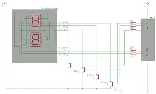
  • Use of 4 transistors as column drivers will probably make a significant difference.

  • Use of a low side segment buffer IC plus high side transistors will give you all the drive you want.

  • Ports are presently being used "illegally" but damage is not occurring due to low drive of processor relative to LEd current ratings. Once proper drive is available series resistors will be needed to prevent damage.


Here is the data sheet for the 74HC244 buffer mentioned by arminb.
It provides 8 x inverting buffers.
The non inverting version is the 74HC240 - datasheet here .
Both these are OK in principal but notionally only provide 8 mA drive per circuit.

You can get various higher current versions such as these SN74LVC244a in stock at Digikey at 26 cents in ones - a bargain! :-).

Driving LEDS without resistors from a processor is bad practice whether it "works" or not. It loads the IC into "illegal" areas if it doesn't work and risks damaging the display if it does work (and still loads the IC illegally).

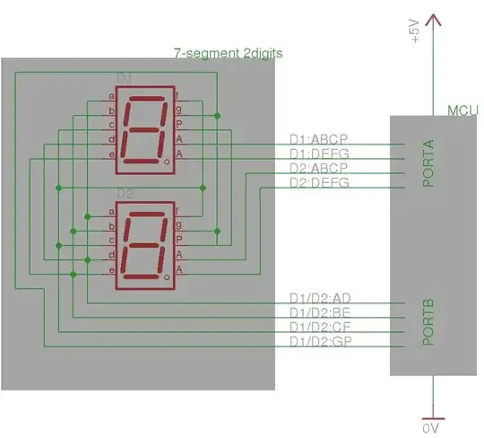
Your display currently drives 4 segments at a time x 4 columns.

IF you have 4 more port pins available you can (probably) double the brightness of your display by driving 8 segments at a time x 2 columns x 2 port pins per column. This allows you to multiplex your display at twice the rate so twie as bright IF current is maintained - which is why I doubled up the column drives.

At present you are driving a column of 4 LEDs via a portA pin but sinking it via 4 x port B pins. If you have 4 segments on then the brightness is limited by the ability of the single Port A pin to supply 4 x LEDs. If there is only one segment per column on then PortyA supplies one LED and port B sinks 1 LED BUT sink capacity is usually greater than source capacity on many processors, so PORT A drive will still probably be the limit.

SO by providing 4 x port A high side drivers you should increase brightness. These can be as simple as 4 x transistor emitter followers.
4 x NPN transistor (BC337 or similar)
Collectors to V+
Bases to Port A pins
Emitters to LED Anodes.

Adding a series resistor per LED would be "a good idea" [tm].

Knowing what your port pin source and sink capabilities are is essential if you wish to design the result.
Telling us what your processor is and providing links is always an extremely valuable thing to do.

If using transistors as above does not work well enough you can add per segment drive as well by using an octal buffer, as above, or by using segment drive transistors.

For a low side driver an eg ULN2803 octal driver would do an extremely good job. Using one of these plus high side emitter followers without a series resistor would produce a very very very bright display, but only for one cycle :-(. Yu can get other members of the ULN280x family which have different input drive requirements but the '2803 is generally the most useful.

Russell McMahon
  • 147,325
  • 18
  • 210
  • 386
  • Thank you. I decided to use the emitter follower. It works very well. I've updated my question with the final schematics. – arminb Jun 10 '12 at 13:57
2

I would just throw an HC244 octal buffer in line with your output ports, since they can usually source 20mA or so. Remember your current-limiting resistors. You could also use transistors if you wanted to, but I think the single IC method is the easiest.

Here is a link to the manufacturer's part that I thought would do the trick for you.

Dave
  • 3,800
  • 24
  • 41
  • What are octal buffers? I can't find any description on the internet... weird. – arminb Jun 07 '12 at 22:59
  • https://www.google.com/search?q=hc244+filetype%3Apdf&ie=utf-8&oe=utf-8&aq=t&rls=org.mozilla:en-US:official&client=firefox-a – Dave Jun 07 '12 at 23:20
  • Don't use Google links. Better link to one specific device, preferably a [datasheet](http://www.nxp.com/documents/data_sheet/74HC_HCT244.pdf) at a manufacturer's site. If you also take the trouble to read it, you'll see that it only gives you 6mA, not 20. BTW, you do know how much the anodes, need, don't you? – stevenvh Jun 08 '12 at 07:17
  • Ok, here's the one I had been looking at. Thanks for the suggestion about linking to the manufacturer's site, I should have done that. http://www.fairchildsemi.com/ds/74/74VHC244.pdf – Dave Jun 08 '12 at 13:55
  • :) I know how to do that. I just figured people would read the comments and it wasn't a big deal because this isn't the right answer anyway. – Dave Jun 11 '12 at 14:47
  • @Dave - The link to the manufacturer's part is relevant. Sometimes there are small differences between manufacturers and then it's a good thing that everybody talks about the same device. – stevenvh Jun 11 '12 at 14:51