6

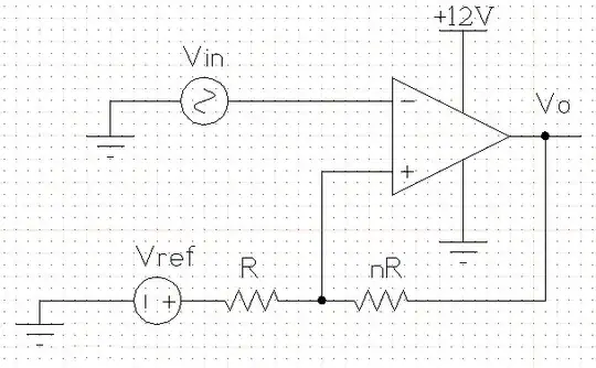
I'm trying to be sure I'm computing the values for this circuit right. Here's an example of the circuit I'm trying to build (it's going in a 12 V DC system, so I filled that in already).

Inverting comparator circuit with hysteresis

I have a textbook from electronics class several years ago (which is where the circuit design came from), and it has these formulas:

\$ V_{h}=hysteresis~width \$

\$ V_{ut}=upper~threshold~voltage \$

\$ V_{ctr}=center~of~threshold~voltages \$

\$ V_{lt}=lower~threshold~voltage \$

\$ V{ref}=comparator~reference~voltage \$

\$ n=resistor~multiplier~for~the~hysteresis~divider \$

\$ V_{h} = V_{ut}-V_{lt} \$

\$ V_{ctr}=\dfrac{V_{ut}+V_{lt}}{2} \$

\$ n=\dfrac{+V_{sat} -(-V_{sat})}{V_{h}}-1 \$

\$ V_{ref}=\dfrac{n+1}{n}V_{ctr} \$

So according to this, if I want the comparator that has Vut = 7 V and Vlt = 6 V I should have n=11 and Vref = 7.09 V to match my Vsat+ = 12 V and Vsat- = 0 V.

In ngspice (using an LF411 model from National Semiconductor) these values simulate an output that is more like Vut = 7.5 V, Vlt = 6.5 V. I even used exact resistor values (R = 10 kohm, nR = 110 kohm) instead of closest-available.

Is this a good circuit to use for my purpose? Should I normally have to tweak these values for real life? I've found that R = 10 kohm, nR = 75 kohm, and Vref = 6.5 V get me closer to the Vut = 7 V and Vlt = 6 V that I wanted, but those values are pretty far off from expected.

Peter Mortensen
  • 1,676
  • 3
  • 17
  • 23
Matthew
  • 289
  • 2
  • 3
  • 8
  • 1
    As user *user1443332* mentioned, this circuit is not likely to work for all input. BI-FET op-amps are especially susceptible to phase reversal. The datasheet for LF411 even mentions this: "Exceeding the negative common-mode limit on either input will force the output to a high state, potentially causing a reversal of phase to the output." – Peter Mortensen Apr 06 '15 at 07:52

2 Answers2

5

You should see immediately that the 7.09V can't be right. 7.09V on one end of the resistors and 12V on the other end can never give you 7V on the non-inverting input. Your equation for \$V_{REF}\$ seems to be wrong.

Here's how I do it. Since the current through the resistors is the same we have

\$ \begin{cases} \dfrac{V_{SAT+} - V_{UT}}{nR} = \dfrac{V_{UT} - V_{REF}}{R} \\ \\ \dfrac{V_{SAT-} - V_{LT}}{nR} = \dfrac{V_{LT} - V_{REF}}{R} \end{cases} \$

Filling in the parameters and eliminating R:

\$ \begin{cases} \dfrac{12V - 7V}{n} = 7V - V_{REF} \\ \\ \dfrac{0V - 6V}{n} = 6V - V_{REF} \end{cases} \$

From the second equation:

\$ V_{REF} = \dfrac{n + 1}{n} 6V \$

Replacing \$V_{REF}\$ in the other equation:

\$ \dfrac{12V - 7V}{n} = 7V - \dfrac{n + 1}{n} 6V \$

We find \$n =11\$, that's also the value you found. But my \$V_{REF}\$ is different:

\$ V_{REF} = \dfrac{n + 1}{n} 6V = 6.55V \$

This is OK for a theoretical calculation, but in practice you may have a problem: do you have a 6.55V source? The typical way to solve this is to get a reference voltage via a resistor divider from your 12V power supply, and then you get this circuit:

enter image description here

We still have 2 equations, but three unknowns, so we can choose 1. Let's pick a 30k\$\Omega\$ for R3. Then, applying KCL:

\$ \begin{cases} \dfrac{12V - V_{UT}}{R1} + \dfrac{V_{SAT+} - V_{UT}}{R3} = \dfrac{V_{UT}}{R2} \\ \\ \dfrac{12V - V_{LT}}{R1} + \dfrac{V_{SAT-} - V_{LT}}{R3} = \dfrac{V_{LT}}{R2} \end{cases} \$

Filling in our parameters:

\$ \begin{cases} \dfrac{12V - 7V}{R1} + \dfrac{12V - 7V}{30k\Omega} = \dfrac{7V}{R2} \\ \\ \dfrac{12V - 6V}{R1} + \dfrac{0V - 6V}{30k\Omega} = \dfrac{6V}{R2} \end{cases} \$

That's

\$ \begin{cases} \dfrac{5V}{R1} + \dfrac{5V}{30k\Omega} = \dfrac{7V}{R2} \\ \\ \dfrac{6V}{R1} - \dfrac{6V}{30k\Omega} = \dfrac{6V}{R2} \end{cases} \$

From which we find

\$ \begin{cases} R1 = 5k\Omega \\ R2 = 6k\Omega \end{cases} \$

stevenvh
  • 145,145
  • 21
  • 455
  • 667
  • Ha! CircuitLab! Link – clabacchio Jun 08 '12 at 09:36
  • The calculations are correct but the OP's assumptions about Vsats of 0V & 12V won't hold for the LF411! – MikeJ-UK Jun 08 '12 at 15:41
  • @Mike - True! But his problems started already before the simulator: his equation for Vref from his textbook is wrong. – stevenvh Jun 08 '12 at 15:51
  • Your second circuit worked wonders for me! Thanks! Sometimes I have a little bit of a hard time following the formulas though, and I couldn't figure out where the equation Vref=((n+1)/n)6V came from. It's labeled "from the second equation" but I'm still not seeing it. Sorry I'm a little slow at this after years of being out of it. ;) – Matthew Jun 08 '12 at 16:07
  • @Lytithwyn - `-6V / n = 6V - Vref`, then `-6V / n - 6V = -Vref`, then `6V x (1/n + 1) = Vref`, then `6V x (1/n + n/n) = Vref`, then `6V x (1 + n)/n = Vref`. Write each step down, and you'll see it's very easy. (Out of it since 25 years ;-)) – stevenvh Jun 08 '12 at 16:26
  • Duh...got down to the last step on my own and didn't see that I could factor out the 6. Thanks a bunch. (And to be honest, the only _in it_ I ever was included a few classes ;) ) – Matthew Jun 08 '12 at 17:00
  • @Mike What you were saying about 0V & 12V...did you mean the fact that the real output is more like 10V and 1V? Or are you saying those voltages won't work as Vcc & Vee for the LF411? The datasheet just says "supply voltage +/- 18V". Does that mean anything inside that range? – Matthew Jun 14 '12 at 21:21
  • @Lytithwyn - the first thing. In the [datasheet](https://www.national.com/ds/LF/LF411.pdf) look for the term "output voltage swing", which is \$\pm\$ 13.5 V typical for \$\pm\$ 15 V power supply. – stevenvh Jun 15 '12 at 04:55
1

Assuming the comparator doesn't draw any current on its input pins, we have

i (from output of comp to Vref) = (Vo-Vref)/(R+nR). 

So V+ (+ input comp):

V+ = (Vo-Vref)*R/(R+nR) + Vref

Which give us:

Vbottom = (Vss - Vref)*(R/(R+nR)) + Vref

And:

Vup = (Vdd - Vref)*(R/(R+nR)) + Vref

Assuming Vss and Vdd are your negative and positive power supply. Then isolate for what you want.

Now, is it a good circuit? It depends on what you want to do and you would have to think about, in no particular order:

  • Is the comparator sufficiently fast for the signal you put in.
  • Is Vin a high impedance source? Because there will be some pF of parasitic capacitance to ground on the negative input of the comparator, so it might act as a low pass filter.
  • Your comparator is inverting, is this really what you want? (that is, if Vin > Vup => Vo = Vss)
  • Did you provide adequate supply decoupling?
  • Also, if you are abusing an op-amp as a comparator, you should be very careful, for several reason, it will be (in general) quite slow, your op-amp input common mode range might not include the range of Vin, which might cause latch-up, phase reversal and other non-specified behaviors, they might saturate and be slow to recover, etc... (see Amplifiers as comparators? for an article about abusing op-amps as comparators).
Peter Mortensen
  • 1,676
  • 3
  • 17
  • 23
user1443332
  • 119
  • 1
  • 1
    Welcome! You can use the MathJax engine to type Latex formulas, with much better results – clabacchio Jun 08 '12 at 12:48
  • "sufficiently fast". Has nothing to do with his calculations. "so it might act as a low pass filter". Idem. "Your comparator is inverting". This is a Schmitt-trigger. "adequate supply decoupling". Has nothing to do with his calculations. And so on. Also you don't verify his n and Vref, you don't finish the calculations. – Federico Russo Jun 08 '12 at 16:16
  • I did intend for it to be inverting actually. Slow isn't a problem either...there should be whole minutes between crossings in my application. Thanks for the good questions and the link! – Matthew Jun 08 '12 at 17:04
  • @clabacchio Thanks for the tip about MathJaX. I updated the question with pretty equations. – Matthew Jun 08 '12 at 21:34