I see several options for this; there is the TI's application bulletin (originally a Burr Brown App. Bull. from 1997) --- www.ti.com/lit/an/sboa068/sboa068.pdf
There's LT's LT1001-based circuit: http://cds.linear.com/image/416_circuit_1.jpg
Then, there is the simple circuit shown in Wikipedia's Precision rectifier page:
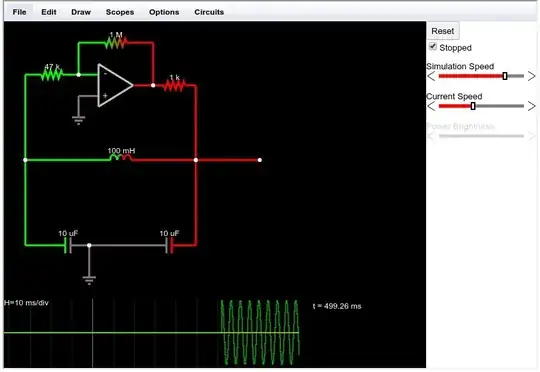
simulate this circuit – Schematic created using CircuitLab
which I can combine with the original signal (i.e., its output + Vin/2) to obtain the absolute value of the input signal:
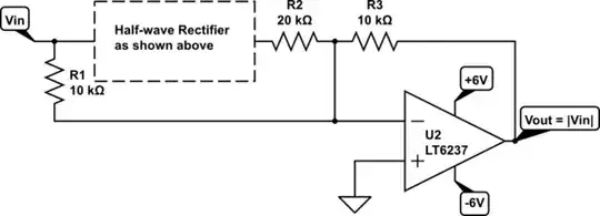
Notice that I indicated LT6237; among other things, I need moderately high bandwidth (I want the absolute value of signals going up to 10 or 20 MHz).
I find this the simplest option, and can't see any obvious disadvantages --- are there any important advantages in the other designs with respect to this one?
All circuits are sensitive to resistors mismatch; I'm planning to use 0.1% resistors either way. But I wonder: are some of the circuits especially sensitive to resistors mismatch?
I believe that one advantage of this one is that neither of the two op-amps has the other op-amp in its feedback path (which the other two designs do, at least for a fraction of the input signal cycles), so if we have stable op-amps, then we do not need external compensation capacitors. Is my intuition correct?
With the above said: I run a simulation with LTSpice, selecting LT6237 for the op-amps, and the circuit behaves wildly different depending on the diode that I select. For the resistors, I use the ideal/generic resistor from the LTSpice tool bar. If I select the generic/ideal diode, then the circuit oscillates when the output goes positive. With 1N4148, it does not. With fast-recovery diodes (the first fast recovery from the list), the output is wildly distorted (no oscillation, but the output is quite deformed), for Schottky (e.g., 1N5817), the circuit oscillates.
Are these simulation artifacts? What should/could I expect in practice when assembling the actual circuit?
Thanks!