14

I made a series of PCBs to power some solenoid valves that use an external power supply. I switch them with BS170 MOSFETs using an Arduino as gate signal. I based it a solution by Jason S.

This is an illustration of what my circuit looks like: MOSFET operated valve circuit

On testing the PCBs, I noticed that most of them work fine, but some of them don't. No problem, probably a soldering thing.

However, those faulty ones did manage to destroy two Arduino digital pins! On one, I get a constant voltage of 5 V, and the other one outputs 0.2 V when I send a HIGH signal to it, and 0.5 V when I send a LOW signal. Strange stuff.

So I guess the faulty circuits somehow caused (some of) the 16 V to flow through the Arduino, destroying them.

How do I protect the Arduino in this scenario from too high current?

I know about zener diodes, but I have no idea how to place them to protect the inputs.

Technical information:

Dyte
  • 443
  • 3
  • 5
  • 13
  • What software did you use to create that drawing? It looks really good! – mjh2007 Jun 06 '12 at 21:26
  • 3
    Fritzing. Free and very handy for this kinds of stuff, also for pcb design :) – Dyte Jun 06 '12 at 21:28
  • Gate-source zener diode of say 12V (> Vgate_drive) is a very good idea indeed in all circuits with inductive load. Mount zener close to MOSFET. Anode to source and Cathode to gate so zener does not usually conduct. || Far far far better MOSFETs at 26c/10 Digikey are eg [IRLML6346](http://www.digikey.com/product-detail/en/IRLML6346TRPBF/IRLML6346TRPBFCT-ND/2538169) SOT23. Or [NDT3055 48c/10](http://www.digikey.com/product-detail/en/NTD3055L104-1G/NTD3055L104-1GOS-ND/1484764) TO251 leaded, or [RFD14N05 71c/10](http://www.digikey.com/product-detail/en/RFD14N05L/RFD14N05L-ND/458750) TO220. – Russell McMahon Jun 07 '12 at 02:12
  • `...When MOSFETs fail they often go short-circuit drain to gate...` Cited from [here](http://www.4qdtec.com/mostest.html#Dead). – abdullah kahraman Jun 08 '12 at 07:27
  • Applying 16V may kill your Arduino ports. – abdullah kahraman Jun 08 '12 at 07:28
  • Are you really sure the transistor is connected correctly. Usually the center lead is also conntect to the power tab, which is the collector of bipolar transistors and the drain of FETs. You show the center lead connected to the arduino. Double check this. – Olin Lathrop Jun 08 '12 at 11:49
  • @OlinLathrop he is using a [BS170](http://www.fairchildsemi.com/ds/BS/BS170.pdf) in a TO-92 package which seems okay in the diagram apart from the package type. – abdullah kahraman Jun 08 '12 at 16:38
  • @abdullahkahraman - Your reference said "often go short from draihn to date" - which is true,. But they can do just about anything else instead or as well. I thinj ==k his point is that you can see the drain voltage applied to the gate and have to be prepared for this - which is a very good point. I have seen many many many power MOSFETs fail :-). Common is D-S hard short with or without gate connected to the DS short. Sometimes you get just D-G. More rarely you get open circuit on all terminals. Power Zeners (say 1 Watt+) tend to fail hard short but even that is not reliable with some O/C. – Russell McMahon Jun 09 '12 at 17:17
  • @RussellMcMahon supercat mentioned about some protection methods in one of [his answers](http://electronics.stackexchange.com/a/30044/5035). Also the reference I gave mentions sub-miniature gate resistors which fail open-circuit, acting as fuses. – abdullah kahraman Jun 09 '12 at 18:14

6 Answers6

10

Your valve is rated at 500mA at 12V. If you supply 16V it will draw somewhat more than 500mA. Assuming it is a resistance, it will draw 667mA.

The absolute maximum current for the MOSFET you used is 500mA continuous. Anything above absolute maximum ratings may destroy the device. This is probably why you are seeing reliability problems.

There is no guaranteed failure mode for MOSFETs, so I'm not surprised that it would fail in such a way to damage the Arduino outputs.

As Jason mentioned in the linked answer, BS170 is a poor choice of MOSFET. You need a better one. Choose one in a TO-220 case that is rated at several amps. You also need to make sure the Vgs is rated for 5V logic-level drive.

Which diode are you using?

markrages
  • 19,905
  • 7
  • 59
  • 96
7

The circuit is fine in theory.
Improvement in practice is required.

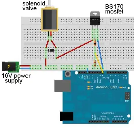
Adding a gate-source zener diode of say 12V (> Vgate_drive) is a very good idea indeed in all circuits with inductive load. This stops the gate being driven destructively high by "Miller capacitance" coupling to the drain during unexpected or extreme variations in drain voltage.

Mount the zener close to the MOSFET.
Connect Anode to source and Cathode to gate so that the zener does not usually conduct.

The 10k gate drive resistor (as shown) is large and will cause slow turn off and on and more power dissipation in the MOSFET. This is probably not a problem here.

The chosen MOSFET is very marginal in this application.
Far far far better MOSFETs available ex stock at Digikey include:

For 26c/10 Digikey IRLML6346 SOT23 pkg, 30V, 3.4A, 0.06 Ohm, Vgsth = 1.1V = gate threshold Voltage..

NDT3055 48c/10 TO251 leaded 60V, 12A, 0.1 Ohm, Vgsth = 2V

RFD14N05 71c/10 TO220 50V, 14A, 0.1 Ohm, 2V Vgsth.


ADDED

SUITABLE MOSFETS FOR 3V GATE DRIVE:

System just trashed my longer answer :-(. So - MOSFET MUST have Vth (threshold voltage) of no more than 2V to work properly with 3V3 supply controllers.
None of the suggested FETS meet this requirement.
They may work after a fashion on the present load but are underdriven and overly lossy and the solution does not extend well to larger loads.
It seems that IRF FETS in size range concerned that have Vth (of Vgsth) <= 2 volts ALL have 4 digit numerical codes starting with 7 except IRF3708.

OK FETs include IRFxxxx where xxxx = 3708 6607 7201 6321 7326 7342 7353 7403 7406 7416 7455 7463 7468 7470

There will be others but all the ones suggested seem to have Vth = 4V or 5V and are marginal or worse in this application.

Vgsth or Vth needs to be at least one Volt less and ideally several volts less than actual gate drive voltage.

Russell McMahon
  • 147,325
  • 18
  • 210
  • 386
  • Yeah, I'm going for the safe way and I'll use another mosfet. That and the zener diode should probably do the trick. In the electronics shop close to where I live they don't have the mosfets you proposed, but they do have: IRF520, IRF530, IRL530, IRF540, IIRF730, IRF740, IRF830, IRF840, IRF9140, IRF9530, IRF9540, IRF9610, IRFBC620, IRFDD110, IRFD9120, IRFP50, IRFP054, IRFP140, IRFP150, IRFP450, IRFP520, IRFP9140, IRFZ44, IRFZ46. I suppose I could go for an IRF520 for example? continuous drain current is 6.5 to 9.2 A. Min Vgs is 2V and max is 4V, is that ok though for the arduino? – Dyte Jun 07 '12 at 14:41
  • The IRF520 is fine for an Arduino to drive. Min Vgs and "max Vgs" aren't quite what you think, that's the "treshold" voltage, where the MOSFET starts conducting. Maximum Vgs is substantially higher (above the 5v the Arduino will output). Exceed that higher rating (20V?) and you'll bust the FET. – Bryan Boettcher Jun 07 '12 at 16:39
  • It works using the IRF520 MOSFET and a 5.1 V zener diode, and will probably keep on working this time :) Thanks a lot for helping me out. All of the answers helped me, but you elaborated on zener diodes and specific types of mosfets, so I'm accepting yours as answer. – Dyte Jun 07 '12 at 18:12
  • @Russell McMahon: The voltage my arduino outputs is (a little less than) 5V, not 3V3. Doesn't that change the situation? – Dyte Jun 08 '12 at 20:48
5

Your valve is rated for ~ 500 mA. A BS170 is rated for 500 mA too, but that is the sales-pitch figure. I would use a (much) higher rated FET here, 500mA through a TO92 makes me nervous. And you have a 1k gate resistor, which is a good idea in most cases, but it might cause the poor FET to switch too slowly to survive the 0.5A.

What diode are you using? It must be rated for the 0.5A, so a 1n4148 won't do. I am not sure, but it might actually get more than 0.5 because the moving part of the value might cause an even larger spike than a plain coil would.

In your picture you have the value return current flowing past the Arduino ground connection. I would cange that to a star: connect the arduino ground to directly to the power supply. Or much better: use an optocouple to isolate the high-current circuit from the Arduino (and use two separate power supplies).

Wouter van Ooijen
  • 48,407
  • 1
  • 63
  • 136
  • The diode I use is a 1N4001. http://www.diodes.com/datasheets/ds28002.pdf I didn't think of an opto coupler. That's a good scenario to investigate :) – Dyte Jun 06 '12 at 21:26
5

You should have a gate-source resistor on your MOSFET so that the gate cannot float up if the Arduino output is high-impedance. Since the solenoid power supply and the Arduino power supply are separate, this scenario could happen (unless you guarantee by design that the Arduino is always on first.)

Is the MOSFET actually so far from the solenoid? If so, it should be moved much closer. Move it so that the drain directly plugs into the protoboard strip where the red wire goes to the solenoid and the diode. Then make a short source connection to the GND strip. It's better to have a longer gate signal loop (at low power) vs. a long loop that carries power. You could move the Arduino closer to the solenoid as well, keeping all those loops short.

Adam Lawrence
  • 32,921
  • 3
  • 58
  • 110
  • By a gate-source resistor, do you mean a resistor between the gate and source of the mosfet? Sorry if this is a dumb question :). What value do you suggest? About the distances, no, all the components are close to each other, I have this circuit soldered on a self etched PCB. Only the wires to the arduino are longer. I have to say though, I had no idea that this made any difference. I thought the difference in time that current travels a few cm further was negligible. – Dyte Jun 06 '12 at 22:02
  • @Dyte Yes, a resistor between the gate and source. – Adam Lawrence Jun 07 '12 at 13:59
  • @Dyte, I imagine a 10k gate-source resistor would be fine. The goal is just to make sure that the gate of the MOSFET doesn't float. You want something low enough that can "win" against parasitic circuit elements, but high enough that the Arduino output can "win" when it needs to turn the MOSFET on. – ajs410 Jun 08 '12 at 20:03
3

The circuit as illustrated looks fine, provided the only ground connection between the Arduino board and the negative terminal of the +16 supply is the short blue wire. On the other hand, it's possible that accidental shorts could cause bad things to happen. It's hard to guess exactly what might have happened without seeing how the actual problematic boards were laid out.

If you are pushing the specs of your MOSFET, it could easily fail in such a way as to sent +16 out the gate, but if the resistors are as illustrated I would expect the Arduino should be pretty well protected.

supercat
  • 45,939
  • 2
  • 84
  • 143
1

First of all, you need ultrafast switching diodes not these cheap 2n4001-4 diodes, when using motors or coils. The faster the switching, the greater BEMF is created. Also use a 914 switching diode to the mosfet gate from the arduino, and a 10k pull/down resister from gate to ground.