28

the (surely simplistic) model of a bipolar junction transistor one is taught in foundational physics course appears to be symmetric. - So, what is the difference between the collector and the emitter of a real BJT? If the transistor were symmetric one would not make this distinction...

Also:

  • Do BJTs have a 0.6V voltage drop like diodes?
  • Are BJTs conductive in both directions, i.e. E-C and C-E?

Many thanks.

ARF
  • 5,169
  • 9
  • 42
  • 69

1 Answers1

24

Yes, BJTs have the same voltage drop across their junctions as common diodes, that's 0.6V to 0.7V between base and emitter, and the same between base and collector. Since the junctions act like diodes they don't conduct in both directions if you apply a voltage across the two pins.

When you use an NPN transistor as a transistor, current will from collector to emitter through the base, even though the base-collector junction reverse biased.

enter image description here

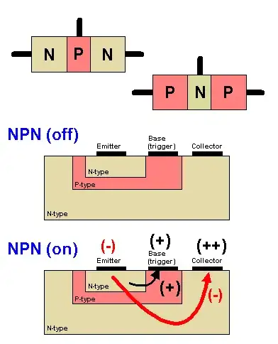
The arrows indicate electron flow, not conventional flow. Conventional flow is from positive to negative and is always used in circuit analysis. But conventional flow can't explain the details of the working of a transistor, so here electron flow is shown.
Also note that the collector voltage is higher than the base voltage.

The main differences between emitter and collector are doping concentration and size. The emitter is heavily doped, while the collector is lightly doped. You could try to swap them, but you'll get a very low \$H_{FE}\$, probably even less than 1.

stevenvh
  • 145,145
  • 21
  • 455
  • 667
  • Many thanks, that makes sense. You write that for NPN the BC junction is reverse biased when transistor is conducting. What happens if the base is negatively biased w.r.t. the emitter? Would it then be forward biased? – ARF Jun 05 '12 at 12:23
  • @Arik - No, both will be reverse biased. Draw an NPN with the voltages on each pin. Draw an arrow for the base-collector junction. You'll see that the base (the anode for both diodes) is negative for both, so there won't be any current. Note that the base-emitter junction only can stand a few volts reverse. – stevenvh Jun 05 '12 at 12:31
  • @stevenvh, on your last picture you show the arrow going from emitter to trigger as a + but that would also be the direction of electron flow, it is a minor issue but one I could see leading to confusion. I am also used to seeing the collector say "++" to show that you need a higher bias on the collector then the base for the system to actually have gain. – Kortuk Jun 05 '12 at 12:35
  • @Kortuk - OK, clarified. I'll see if I can fix the image (not mine, I found it on Google) – stevenvh Jun 05 '12 at 12:40
  • @stevenvh Thanks for the help and especially for the hint about the maximum reverse bias voltage of the BE junction. – ARF Jun 05 '12 at 12:43