6

I understand that in a Class AB amplifier, a pair of diodes are placed between the bases of the two transistors to slightly forward bias both bases.

Why are diodes typically used to provide the forward bias instead of a single resistor providing a voltage drop of 1.2V? (Is it because changes in temperature will affect the forward bias of the transistors and the diodes in roughly the same way?)

talikarng
  • 141
  • 2
  • 8
  • Changes in current will do almost nothing with diodes. BTW, the temperature drift should cancel out, the base-emitter junctions should be affected in the same way as the diodes. – Oskar Skog Oct 06 '17 at 04:10
  • 1
    Diodes aren't really all that great, but they are easy to understand and they are cheap and their voltage varies with temperature in the same direction as does the \$V_{BE}\$ of the output BJT pair (I have to assume you are talking about only two BJTs here.) And their voltage is fairly stiff vs the current, so they do well where some of the current is being borrowed to operate the BJTs. But the diodes need to be thermally coupled to the BJTs and their variation with temperature is on a different slope (usually.) So a \$V_{BE}\$ multiplier is often a better choice. A resistor is a bad choice. – jonk Oct 06 '17 at 04:25
  • Okay, what makes the resistor a bad choice? – talikarng Oct 06 '17 at 04:47
  • The base-emitter junction in the BJT *is* a diode, and preferably the diodes you are talking about should be chosen so that they perform as close as possible similarly as the base-emitter diode. – PkP Oct 06 '17 at 04:49
  • 1
    @talikarng I already addressed a reason why in my comment, where I say "current is being borrowed..." (There are several other good reasons.) Designers actually work hard to reduce the incremental resistance of this Vbias system, going to the extra trouble of designing and using an Early Effect countering collector resistor in the multiplier, as well, so they can make the peaking characteristic nearly perfectly flat at one current. Beyond this, I'd need to write an answer. No time right now. I'll add a few links you can peruse from here, though. Might help. – jonk Oct 06 '17 at 05:26
  • @talikarng https://electronics.stackexchange.com/questions/281753/cant-understand-an-ab-amplifier-diagram/281838#281838 , https://electronics.stackexchange.com/questions/325384/bjt-2-stage-amp-output-problem/325502#325502 , https://electronics.stackexchange.com/questions/273867/transfer-function-of-a-lm380-power-amp/273901#273901 – jonk Oct 06 '17 at 05:27

3 Answers3

7

The answer is that it varies with the needs for the design. You can use resistors to bias an AB class amplifier (just look for Class AB on Google images to see a huge variation in designs), though typically you will see some other schema for setting the bias current through the output pair, or a constant current drive for the bases.

A lot depends on whether you are setting very low class A capability or not. When using two diodes to bias the output pair you are operating very close to Class B only.

In the schematic below it shows both low and high A bias:

enter image description here

What you describe with two diodes (which have Vf close to the Vbe of the output pair) are operating at very low Class A current. Typically you might see this in a 5-10 W or so amplifier. Operation in Class A (linear) may only be 200-300 mW. These amplifiers turn up in battery powered products a lot since they have low bias current

In the second circuit there are 4 diodes, and you'll see this commonly in high power (50-100 W) mains driven amplifiers. Here the linear operation may cover 5 W or more. This is done so that when you plug in a headset you typically only use the output as a Class A stage with very low distortion.

The two diode bias obviously tracks better thermally than the four diode amplifier, but the larger amplifier is more capable and the output stage has larger heatsinks.

In terms of understanding this type of amplifier you can do no better than read the Linsley amplifier design, done before the days of FETs.
Equally great reading is Blomleys 'New Approach' design. These guys were at the forefront of amplifier design in the 70's, but FET based designs changed it all.

Jack Creasey
  • 21,428
  • 2
  • 15
  • 29
6

The base-emitter junction in the BJT is a diode, and preferably the diodes you are talking about should be chosen so that they perform as close as possible similarly as the base-emitter diodes.

This way the operation of the transistor stage of the AB class amplifier is already quite close to what you are looking for even without the negative feedback from the output to the op-amp before the transistors, and the negative feedback thus has less errors to correct.

Near the zero cross-over region, when the input signal is near zero volts, due to the diodes both transistors are quite close to starting to conduct instead of 0.7 volts away from that point. This way there are no dramatic transients required in the feedback signal.

PkP
  • 7,567
  • 2
  • 23
  • 42
0

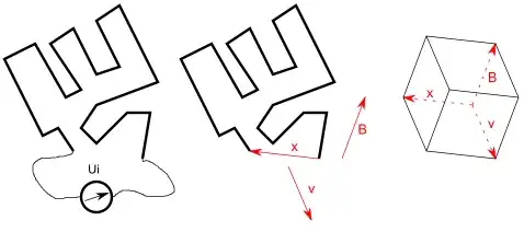
How does one achieve "tight thermal coupling", so the diodes track the transistor temperature?

You cannot achieve tight thermal coupling, unless the diode and the transistor share the same silicon die, and the diode is interdigitated into the transistor's emitter stripes.

Even if on the same heatsink, with 10cm spacing (copper heatsink), the thermal tau is 96 seconds. With 1cm spacing on copper, the thermal tau is 0.96 seconds. Note with 0.96 seconds delay, even the bass tones will not be tracked by the diode/transistor combo.

On the same silicon die, with 1cm spacing, the tau is 1.14 seconds; at 1mm spacing (0.04 inches), the tau is 11.4 milliSeconds, thus some of the bass tones are tracked. At 0.1mm (100 micron, or 4 mils or 0.004"), the tau is 114 microseconds, thus tones up to 1KHz are well coupled. By the way, no one is going to include a 1cm open region between the hot transistor and the diode; they will fill in that region with useful components. However, I've seen large die with hundreds of microns of distance between the hot transistor and the sensor, with the design-team wondering why the overtemp protection does not protect. Simple: there is a big delay, and the hot device simply gets melted long before the shutoff can start.

One may ask a different question: what kind of coupling is needed? to track the realtime thermal transients during the music? or to track the longer term changes in the heatsink temperature, as the power amplifier heats up or the entire room changes temperature.
analogsystemsrf
  • 33,703
  • 2
  • 18
  • 46
  • 1
    There is absolutely no need to thermally track the diode/Vbe pair during audio peaks. The amplifier will be drawing much more current (ie delivering power to the output). It is only necessary to track the Class A current in the quiescent state. It is easy to measure the difference between one output device supplying high power and one at quiescent. It is only when the quiescent current for both devices rises (since now of this power is delivered as output) that you need to sense it. – Jack Creasey Oct 06 '17 at 16:11
  • Then we can wonder why ONNN Semi sells devices with heat-sensor diodes on the same die as the power bipolar. I'm not disagreeing with your comment, Jack Creasey. – analogsystemsrf Oct 06 '17 at 16:17
  • There are lots of high power applications where a coupled diode or Zener is valuable, audio amps is just not one of them. Can you point to a device or circuit where this is used in audio? – Jack Creasey Oct 06 '17 at 16:27