I know the characteristic impedance to be the square root of the ratio of the impedance (Z) and the conductance (G) of the line, both complex numbers. Hence, the characteristic impedance must be also complex. However, in most problems that I encounter, the characteristic impedance of a given line is almost always just resistive. Why is this?
Asked
Active
Viewed 3,320 times
3
-
A ratio of complex numbers is not necessary a complex number if some other physical constraints exist. You might want to consider this explanation of characteristic impedance, https://electronics.stackexchange.com/a/281545/117785 – Ale..chenski Oct 05 '17 at 18:29
2 Answers
3
Do you think characteristic impedance is purely resistive because it is normally labelled as 50ohm or 75ohm and not in the form a + jb?
If so it means you are confusing transmission lines with conductors and characteristic impedance with regular impedance
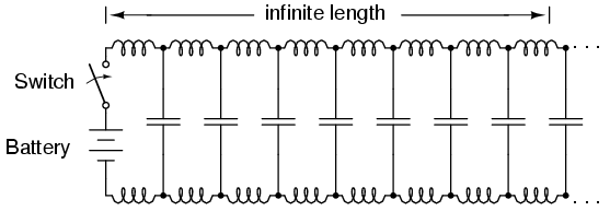
Take an infinitely long line of perfect (no loss) two-line conductor, it will have ZERO resistance but can be 50ohms. The reason is ANY transmission line must have both capacitance (insulation between conductors and voltage difference makes a capacitor) and inductance (current charging the capacitance induces magnetic field which stores energy) as shown in this picture But how does this look like some finite non-complex impedance like 50ohm?
To DC voltage this transmission line looks like a short circuit, but to AC signals:
- The parallel capacitance will cause a splitting of current, which is equivalent (as far as ohms law) to a parallel resistance
- The inductance will prevent infinite AC current which is equivalent (as far as ohms law) to a series resistance
- In both causes there is no loss! just an impedance that LOOKS resistive
- You'll notice that is you buy a cable for RF signals it specifies a frequency at which it LOOKS like 50ohm, this is because the cable is designed such that the capacitance and inductance of the cable resonate and effectively cancel each other out leaving only the effect they have on ohms law meaning there will be an apparent resistive value which is chosen for best power transmission; usually 50Ohms
- In such a cable if you input a frequency higher than its rated frequency it will appear inductive (complex with a positive imaginary term), if you input a frequency lower than its rated frequency it will appear capacitive (complex with a negative imaginary component)
Hope this helps, leave a comment if you want be to elaborate further
source: junior RF electronics engineer, MEng Electrical and Electronic Engineering (2016)
Andrew Davis
- 367
- 2
- 14
1
The characteristic impedance is never purely resistive.
An imaginary component to the characteristic impedance indicates a lossy line, and every real transmission line is lossy.
However, a lossless line is easier to model. If you're doing pen-and-paper calculations, you'll have much less math to do if you are working with a lossless line.
And many lines are close enough to lossless (for the frequency and line length used in a real system) to make the results achieved with the simpler model close enough to be useful. So often we choose to model a line as lossless to make our lives easier while still getting useful results from our model.
Similarly, no wire in a lumped circuit is truly resistance-free, and no real circuit is actually small enough to produce no radiation at all, so every time we use Kirchoff's laws, we're modeling a useful simplification of reality, not a perfect model of reality.
The Photon
- 126,425
- 3
- 159
- 304
-
I just get confused when I encounter problems that gives a purely resistive charateristic impedance, yet they give a value for the alpha (which indicates a lossy line). How can you explain this? – Chaine Oct 05 '17 at 17:11
-
1In many cases, you can model the reflections at discontinuities and terminations with a lossless TL model, and model the losses in propagation separately and still get useful simulation results. – The Photon Oct 05 '17 at 17:14