I would like to point out that I am not an expert (as it is perceived by the question) in the use of scr, diac, and triac and that this question is more for academic purposes than use in real life. Basically, I need to better understand how the scr is commonly used.
I wish to understand how to use SCR in a dimmer with a given heater resistance value and an input voltage frequency value. My goal should be to fully understand how I should pick the other components and if the schematics that I provided below are right or wrong.
The first schematic is very simple. The RC part should activate the SCR during the positive halfwave of the input. For R very small the SCR should be almost always active during the positive halfwave while for R very large the SCR should be almost never active during the positive halfwave. It is correct what I wrote? How should I pick the values for R and C? Supposing I want to keep the SCR active for a given percentage of the positive half-wave, how should I act?
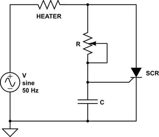
simulate this circuit – Schematic created using CircuitLab
I saw on on schematics that I found on internet that almost all add a diac before the gate of the SCR. What is it's purpouse? How does it change things? I think that is to not stress the gate of the SCR but I'm not sure.
Furthermore, in some cases there is a diode from mass to gate. I think that is because in the input negative half-wave the SCR isn't used but, again, I'm not sure that this is the real and only reason. If a triac is used instead of the SCR the diode is obviously absent.

I know that a real schematic should be much more complex but, for now, I'm interested in keeping it as simple as possible in order to fully understand.