I read somewhere that the addition of R2 provides the DC return to ground however this would reduce the overall input impedance of the op-amp. Input impedance must be high for an op-amp. How to solve this problem? 
Asked
Active
Viewed 4,836 times
8
Transistor
- 168,990
- 12
- 186
- 385
Shivam suhane
- 111
- 1
- 7
-
I have attached a figure now. – Shivam suhane Sep 27 '17 at 19:23
-
Great link provided.explanation given in that question could help me a lot. – Shivam suhane Sep 28 '17 at 03:47
-
@psmears: I think your title edit has misrepresented the OP's question. I think the OP understands the need for DC blocking but didn't understand why the resistor was needed or acceptable. His confusion is that he has been told that "opamp impedance must be high" but thinks that means that any resistance on the input must be high too. Can you edit it back to a better version of the original? – Transistor Sep 28 '17 at 07:19
-
@Transistor: I agree that that's what the OP is asking in the body, but I don't think my edit has changed the meaning of the original title (I was trying to stick as closely as possible to the OP's meaning and words) - certainly the original title didn't mention impedance. Possibly that could be added, but the title is long enough already... can you suggest something better? – psmears Sep 28 '17 at 08:55
-
@psmears: How does it look now? – Transistor Sep 28 '17 at 09:18
-
@Transistor: Definitely an improvement - might have done the same myself but didn't want to go too far from the OP's wording! – psmears Sep 28 '17 at 09:25
-
Please clarify what this circuit is intended to do. – pericynthion Sep 28 '17 at 18:42
4 Answers
8
The opamp input pins have a small bias current. Without R2 in your example the capacitor would gradually charge up or down eventually bringing the pin to V+ or V- and the circuit would no longer work as intended.
I have read somewhere that R2 added provides the dc return to ground however this would reduces the overall input impedance of op-apm.
Yes, so it is important to understand the effect on the circuit.
I/p impedance must be high for op-amp.How to solve this problem?
Not quite right. The op-amp's input impedance is high by design. It will have no objection to being connected to quite a low resistance. For example, if the op-amp is used to measure the voltage drop across a current shunt the resistance might be << 1 Ω.
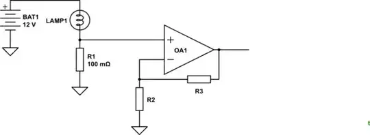
simulate this circuit – Schematic created using CircuitLab
Figure 1. R1 allows OA1 to measure the current through R1, a 0.1 Ω current shunt.
Transistor
- 168,990
- 12
- 186
- 385
-
I read "impedance must be high for op-amp" to mean that he requires the resistance to be high, and adding his R2 lowers the input impedance, and that is the "problem" he wants to solve. It's quite possible I completely mis-interpreted his meaning, I didn't think about the other possibility until I saw your answer. – John D Sep 27 '17 at 19:56
-
Thanks, @JohnD. It's hard to know. Your answer was already up when I posted so I took a different approach. We may both contribute to a better understanding. Let's see if anyone gets "accepted". – Transistor Sep 27 '17 at 20:02
5
The inputs of an op-amp must have a DC path for the bias currents to flow.
You can see in the bipolar op-amp input stage example below that there must be continuous base current flowing:

A continuous current into a capacitor will cause the cap voltage to ramp until it hits some saturation limit, so without a DC path you will likely rail your input.
So you can DC couple the input, use an inverting configuration where the feedback resistor provides the bias current path, or AC couple to an op-amp non-inverting input and provide a resistor to ground or a bias voltage for the bias currents.
If you get a FET input op-amp you can use a very large resistor to provide your DC path and therefore maintain high input impedance.
John D
- 22,677
- 1
- 39
- 56
-
Just a note. Your first sentence particularly applies as a caution for low pass filters, since high-pass often do have a galvanic path for bias currents. – jonk Sep 27 '17 at 19:22
-
-
Looks the OP now has an AC-coupled arrangement, with an added bias current path; or else a high-pass filter. Depending on the precision applied to the design of the capacitor and resistor. (Sloppy, big valued cap means AC-coupled; precise means high-pass.) – jonk Sep 27 '17 at 19:37
5
Why does a resistance is added along with capacitor to block dc component of input voltage in of non inverting ac opamp?
The inputs of an op-amp must have a DC path to allow bias currents to flow and to set the desired DC operating point. If you don't provide a DC path then the likely outcome is that the DC input voltage will drift out of the acceptable common mode input range and your amplifier will not work.
I/p impedance must be high for op-amp.How to solve this problem?
You have two main options. Each has downsides.
- Use a larger resistor. The downside here is that increasing the resistance will increase the output error caused by aplifying the bias current.
- Make the first stage of your amplifier chain DC coupled. The downside here is that DC bias current will be drawn from your external source (and if it can't be drawn you are back to your original problem)
Choosing the right op-amp can help a lot. For example the LTC1052 has an input bias current of 30pA max. So even with a 1GΩ input resistor the bias current would only give you 30 mV max of input voltage error (output error will depend on gain).
Note that if you start using gigohm resistors you will need to ensure your circuit is scrupulously clean.
Peter Green
- 21,158
- 1
- 38
- 76
-
I think adding a capacitor(say C3) in series with R1 and then connect R2 other terminal(which is grounded) between R1 and C3 can help. – Shivam suhane Sep 27 '17 at 20:13
1
Indeed, it is important that the input resistor provides a DC return path so that the bias current will not end up charging the capacitor, which will thereby displace the voltage at the (+) input out of the op-amp's range.
However, another role of the resistor is that it nails down a concrete input impedance that is independent of the choice of op-amp. If we instantiate \$R_1\$ as a \$10\text{k}\Omega\$ resistance, then basically that value is the input impedance of the input. (Based on the hypothesis that the input impedance of the op-amp input \$R_\text{big}\$ is so high that \$R_\text{big} || R_1 \approx R_1\$: we say that the value of \$R_1\$ "swamps" (overpowers) \$R_\text{big}\$.
If we don't nail down a concrete input impedance for the input stage, then the input stage is at the mercy of the specific op-amp part. It could be a million ohms, ten million, hundred million: orders of magnitude variations.
One small problem might be that the impedance is unnecessarily high. Perhaps the circuit driving the stage has minimum load requirements; there are such circuits.
The variation in impedance means that the RC product of the impedance and our coupling capacitor C is an unknown. That's a problem because the input stage constitutes a high-pass filter; if we don't know the impedance behind the capacitor, we don't know what is the knee frequency of this filter.
By designing in the input resistor and capacitor with specific values, we get predictable behavior that we justify with respect to the requirements for the circuit, and which won't change with variations in the op-amp part.
The size of \$R_1\$ also has implications for noise. Without any resistor there, the input impedance is very high, which means that voltage variations (the signal) cause only very tiny current variations. Looked at conversely, what it means is that very little current is required to drive a voltage signal into a high impedance input. The implication is that the situation is susceptible to voltage noise. Sources of voltage noise that are not "backed" by any serious current are able to superimpose themselves on the input signal. If we lower the input impedance with a suitable \$R_1\$, we give the driving device an advantage over voltage noise sources. The driving device has a supply of current behind it and can overpower voltage noises which are not backed by current.
Kaz
- 19,838
- 1
- 39
- 82