25

My MCU runs a SPI bus with about 4 devices. I'd like to extend this bus to be off board as well i.e. have some PCBs connect to the "main" board and extend the functionality. The "pad to pad" distance would be:

trace length of main board + Cable length + trace length on the extending board

3" + 6" + 3" = about 12"

In my experience, even a 1 MHz signal, with about 7 ns rise times, over this distance via a ribbon cable was overshooting by over 1 V (but there was no excessive ringing). The boards will be powered by the same power supply.

enter image description here

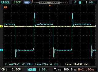
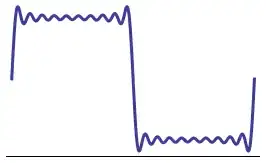
Note: You can't see the rise times here but you can see the excessive overshoot - this is a 3.3V signal. And yes, this was measured properly with a very short wire from the probe to ground. Much like it's often recommend on this site. I don't think it's a measurement error.

I'd like the system to work at 4 MHz but 2 MHz is also acceptable. The max. number of boards I'd like to connect would be about 4 and this would extend the SPI bus to have about 12 devices. I don't think this would be too difficult to manage via code as I already have something working like this. Having the additional slave select lines is also not an issue.

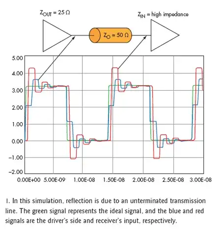
However, my concern is how to send the SPI data from one board to another. Should I just send straight SPI or convert it to LVDS at one end and then convert it back into SPI on the other end?

Saad
  • 5,319
  • 12
  • 60
  • 93

4 Answers4

17

Rule-of-thumb says you have to calculate transmission line effects in if your connection length is longer than 1/10th of the signal's wavelength.

enter image description here

Transmission lines will cause reflections where they show a sudden change in impedance. The reflected signal adds to the original, may reflect again at the transmitter side, and that way go back and forth. The result is shown in the graph: the overshoot you're talking about, and some ringing.

A 12" wire length (30cm) is 1/10 of a 3m wavelength, or 100MHz. 1MHz, and even 4MHz shouldn't give much problems here. Terminating the line, like Wouter says, could be a first measure, though. The input is probably high impedance, and that's never a good matching. Since you have three different pieces in your connection (PCB, wire, PCB) finding the characteristic impedance will be difficult. (It will also be different for the PCB and the wire, so at very high frequencies you'd also get reflections at the cable's connections.) Given the short length and the low frequency the value of your terminating resistor is not critical. 100\$\Omega\$ may be too low for the microcontroller, most of them can't supply 33mA (or even 50mA, at 5V). I would try a 1k\$\Omega\$ resistor to start with, and see how far that gets us.

edit (re question update)
Rise time seems to be 7ns. That's fast, like Kortuk says, it means you have a spectrum at least to 400MHz, and those harmonics will indeed suffer transmission line effects, even if your clock is only 1MHz. Try to filter them out, a 20MHz bandwidth (80MHz for the 4MHz clock) gives you more than enough rise time. This is a 1MHz square wave filtered with a brick wall LPF at 20MHz:

enter image description here

Placing a series resistor will form a first order LPF with the line's capacitance. If we estimate that at 50pF then

\$ R = \dfrac{1}{2 \pi \cdot 100 MHz \cdot 50 pF} =32 \Omega \$

gives you cutoff frequency of 100MHz. So a 33\$\Omega\$ series resistor should decrease your rise time, but leave more than enough to have a good signal at 4MHz.

stevenvh
  • 145,145
  • 21
  • 455
  • 667
  • 3
    The 1MHz frequency is irrelevant. It's the rise time that's important. – Rocketmagnet Jun 03 '12 at 11:38
  • @stevenvh, Tried adding a 1K resistor to ground at the destination. It helped with the spikes but also brought the signal level down a bit. Is that normal? When I say the level where the signal settles down. Also tried 500 Ohms, 220 Ohms same effect but more pronounced. – Saad Jun 06 '12 at 01:25
  • @Saad - How much is a bit? 3.3V in 1k is only 3mA, the driver should be perfectly able to supply that. It may have some internal resistance, but that's a few tens of ohms, so the level should only lower by 2 or 3%. – stevenvh Jun 06 '12 at 04:37
  • @stevenvh I forgot that I series resistor on the line, so obviously I'll drop some voltage. Silly me! However, even a 180 Ohm resistor didn't help much. It brought the overshoot to 4.5V. I'm guessing I'll need a much lower resistance but then I have to worry about current draw. – Saad Jun 06 '12 at 06:49
  • Also, should I consider active termination? Using low resistance will increase power requirements on the entire board and because the bus is operating at all times, it increases the power consumption. Would using Schottky diodes as clamps work well? – Saad Jun 06 '12 at 07:42
  • 1
    @stevenvh how do you arrive at 400MHz? AFAIK from wikipedia BW=0.34/trise. This gives bandwidth of 48MHz. What do I miss? – miceuz Dec 13 '12 at 20:35
8

For such a short bus, I'd try putting a small resistor in series with anything driving a line. That's not the theoretical ideal way taking transmission line theory into account, but a pragmatic approach that I think will work well enough for your case. Try 47 Ω for starters and see what that does. If that helps but not quite enough, you can go higher but I wouldn't exceed 120 Ω. Chances are that somewhere in that range you'll find a value that works well enough.

Olin Lathrop
  • 310,974
  • 36
  • 428
  • 915
  • 1
    I've tried that approach, Olin. I used a 100 Ohm resistor and it dropped the overshoot by about 500 mV and brought it down to 4.3 V from 4.7 V. That's still a volt above 3.3 V! The rise time was then 12 ns as compared to the initial 7. – Saad Jun 03 '12 at 12:20
  • Looks like I was calculating my resistor while you posted your answer, Olin. Sorry about that – stevenvh Jun 03 '12 at 12:31
  • @OlinLathrop I increased the series resistance to 330 Ohms and it brought the overshoot to 3.7V. I'm quite happy with this. The rise time was 10 ns. Should I just stick with this or put in termination resistors on the next revision of the board? I ask because you recommended not to exceed 120 Ohms. – Saad Jun 06 '12 at 07:08
  • @Saad: I was worried about the effect of other loads on the line and it getting susceptible to noise. If the signals are clean and there are no DC loads (just high impedance CMOS inputs, for example) on the lines, then go ahead and use the 300 Ohms. – Olin Lathrop Jun 06 '12 at 11:56
4

AFAIK the overshoot can be eliminated by propper termination, if your driver can drive the load. Otherwise some dedicated driver/receiver pair like LVDS or maybe even RS485 will certainly do.

Wouter van Ooijen
  • 48,407
  • 1
  • 63
  • 136
1

I've had serious problems in the past running SPI over ribbon cables, though ones much longer than what you describe. Noise immunity became a real problem, and corrupted commands ended up getting to my peripherals. It was enough to fail CE noise immunity testing. If you do run into trouble in this regard later on, I'd recommend putting a separate MCU on each board and connecting them via CANbus.

Stephen Collings
  • 17,373
  • 17
  • 92
  • 180