9

I am facing the following problem. I need to power my device (RC airplane) with 2 separate battery packs 12 V each in order to extend the capacity. Connecting them in series will not work, as the power stage is not prepared for that. When I connect 2 battery packs in parallel, and there is a difference in their voltage, they will charge each other, thus a large current will flow making them explode even. I thought of a simple fix for that, it is visible in the below schematics:

schematic

simulate this circuit – Schematic created using CircuitLab

With those 2 diodes I loose some power as voltage drop, but there is no current flowing between the batteries. What If I wanted to add a "voltage" balancing circuit in between them? Lets say if one battery is voltage is only 9 V, because its discharged a little bit, then the 12 V should charge it with set by me current, ie 2 A max. One could design a circuit for that but it would take some time and its not worth for this application I believe. Instead, I wonder either there are such IC's readily available? Bidirectional chargers of some sort? Could not find anything my self, but maybe I dont know how to name them? I would appreciate all help regarding this problem.
Łukasz Przeniosło
  • 1,619
  • 1
  • 19
  • 37
  • I have flown RC airplanes, and never seen your setup. Plus, 12 V is an odd nominal voltage for a LiPo battery... What currents are we speaking of? – Vladimir Cravero Sep 25 '17 at 10:39
  • 12 V is just an example, it is a 3S 3.6V pack. We are talking 25A peak currents. – Łukasz Przeniosło Sep 25 '17 at 10:48
  • 4
    "losing a little power" in the context of electric flight and 25A currents is pretty disastrous. You'd be better to weigh the packs and buy a single larger one approx the same weight. –  Sep 25 '17 at 10:52
  • That would be of course the best solution. But I am trying to take the problem as it is at the moment, before the plane can be physically rebuilt. Besides, I think we are talking about 1V voltage drop loss on the diodes. Correct me if I am wrong. – Łukasz Przeniosło Sep 25 '17 at 10:53
  • *"it is visible in the below schematics: "*. No, it's not. There is no schematic shown, just a black box with a X in it, and "schematic" written to its right. – Olin Lathrop Sep 25 '17 at 11:01
  • Maybe you need to enable some addon in your browser, I am not sure. I have used the schematic editor available in this stack exchange. – Łukasz Przeniosło Sep 25 '17 at 11:03
  • Now the schematic is visible. You may have been editing it when I last tried to look at it. – Olin Lathrop Sep 25 '17 at 11:35
  • 1
    The best solution for this problem is having two identical packs, charge them to the same voltage, connect them in parallel, never charge separately. – Vladimir Cravero Sep 25 '17 at 12:43
  • A 1V drop across a diode times 12.5A flowing through one diode = 12.5W of heat dissipated on each diode alone. I hope you've got really good cooling on those diodes. – tangrs Sep 25 '17 at 14:39
  • Yes, this is in fact a problem – Łukasz Przeniosło Sep 25 '17 at 14:41
  • 1) Get high-power diodes with lower voltage drops. 2) Connect a resistor between the two battery positive leads to balance them. – David Schwartz Sep 25 '17 at 17:01
  • But the resistor would be a plain efficieny loss – Łukasz Przeniosło Sep 25 '17 at 17:07
  • 1
    @Bremen Only if the batteries are actually imbalanced, which the diode scheme will minimize. – David Schwartz Sep 25 '17 at 18:56
  • Your schematic holds the wrong voltages and I wouldn't consider it a battery balancing circuit. You've gotten answers that can only be used partially because of the lack of proper information. Please keep this in mind for your next question. – Mast Sep 26 '17 at 06:57
  • I agree with Vladimir. Charge the batteries, check the voltage with a volt meter to make sure both packs are within 50mV of each other, then put them in parallel. Keep them that way all the time. All the normal precautions for RC batteries apply: assume they may vent or catch on fire at any time and store them appropriately. – user57037 Sep 29 '17 at 04:00

5 Answers5

14

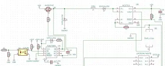
You are much better off making ideal diodes using MOSFETs

enter image description here

  • Replaces a Power Schottky Diode
  • Internal 20mΩ N-Channel MOSFET
  • 0.5μs Turn-Off Time Limits Peak Fault Current
  • Operating Voltage Range: 9V to 26.5V
  • Smooth Switchover without Oscillation
  • No Reverse DC Current

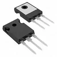
But the simplest solution is a better Schottky Diode Array $6 with a heatsink enter image description here

These are common cathode. enter image description here

Tony Stewart EE75
  • 1
  • 3
  • 54
  • 182
  • 1
    +1 but the current rating needs to be much higher. The OP mentioned peak currents of up to 25A. – tangrs Sep 25 '17 at 14:43
  • MOSFET bridge is not trivial to ensure smooth transfer without oscillation, but gives the lowest voltage drop. As a comparator and timer is used to determined which switches should be active while supplies and load is very dynamic. But with care, may get craft home on standby batteries. The primary cells must not be drained below 9V pref. 10V – Tony Stewart EE75 Sep 25 '17 at 15:00
  • @tangrs actually it is not clear from the OPs comments whether 25A is the run time peak current or the shorted battery current. – Trevor_G Sep 25 '17 at 15:22
  • @Trevor from personal experience in dabbling with building multicopters, it's not unusual to have continuous current draw of tens of amps. These brushless motors can draw a crapload of current... – tangrs Sep 25 '17 at 15:24
  • 4
    @tangrs ya I have zero experience in the field, but still the OP could be more concise. Either way the LTC device shown here won't work at the 3.5V battery level he later added... Question suffers from creeping requirements syndrome...... – Trevor_G Sep 25 '17 at 15:26
  • I was thinking of exacly same fets. The motor is rated 25 A max. There is only one motor. I am not aware how ia the inverter circuitry driving the motor. – Łukasz Przeniosło Sep 25 '17 at 17:02
  • These diodes only drop 0.3V @ 25A @ 125'C – Tony Stewart EE75 Sep 25 '17 at 21:31
  • @TonyStewart.EEsince'75 in fact it is 0.4V, which is 10W; the heatsink will be quite large for an airplane.. Ok, at 25A even a 20mOhm MOS like the one you presented will dissipate a lot (12.5W), so maybe better pMOS should be used... – frarugi87 Sep 26 '17 at 07:35
  • Not really large when you have high air velocity over the surface maybe 5sqin of surface area – Tony Stewart EE75 Sep 26 '17 at 09:02
8

Charging one battery from the other will result in overall drop in efficiency and run time. Consider that energy will be lost in the charging circuit and in heat losses of both the battery powering the charger and the battery being charged.

The most efficient is to take power from the 'good' battery. As its voltage drops to the level of the battery with lower voltage they will both support the load.

When both are charged up your diode arrangement will work and is the simplest solution. With this arrangement the battery voltages will drop at the same rate.

Transistor
  • 168,990
  • 12
  • 186
  • 385
  • Just be aware of how much power is being dissipated across the diode. It's not uncommon to have tens of amps being drawn from the battery in RC applications. – tangrs Sep 25 '17 at 14:42
5

You say series is out... but may have dismissed that too quickly.

You have not really detailed what the power stage requires but I am assuming in this answer it expects some battery like voltage. You have also intimated that the double-up is to extend duration not increase the current available.

As such you may want to consider putting the batteries in series and adding a buck-boost invertor to regulate the output to your required voltage. These can be quite high efficiency and will supply you with your required voltage even when the batteries have fallen significantly below the required output voltage. The power gained from the latter may be enough to compensate for the losses in the regulator.

Trevor_G
  • 46,364
  • 8
  • 68
  • 151
  • 1
    This could work actually (series connection), assuming the flight controller (in this situation Pixhawk + generic ESC drivers) will notice that voltage is higher and will reduce PWM controller for the BLDC's accordingly. A DC-DC converter is not a good idea because the currents can be very high and in that case the DC-DC circuitry size will be large because of capacitors and inductros size. – Łukasz Przeniosło Sep 25 '17 at 13:39
  • @Bremen yup obviously size and especially weight is critical in this application. – Trevor_G Sep 25 '17 at 13:46
  • With the batteries in series, the weak one might be subject to reverse voltages and suffer damage. However, a DC-DC converter need not be heavy if it runs at high frequency where the transformer can be lightweight. – richard1941 Sep 29 '17 at 17:20
2

In your case, assuming the two packs are identical, I would suggest you consider putting the packs in parallel, permanently, to make one pack. Yes, this can be dangerous, but I think it is the only solution that is going to perform for you.

You just need to make sure that both packs have the same voltage when you put them in parallel. The easiest way to do that will be by charging them both fully, one at a time, then measure the voltage for final confirmation, and put them in parallel. If the voltages are different by 0.01V, that is no big deal.

It is kind of customary with RC battery packs to accept a little more risk than would be acceptable in other areas (such as power tools). So just be aware that your pack lacks somewhat in safety features. Treat it carefully and try to always be prepared for it to vent or catch fire. Use safe storage and charging techniques, etc.

This advice would not apply as professional design advice to other battery packs (such as packs used for ordinary consumer products). Those need a lot more safety features.

Happy flying.

user57037
  • 28,915
  • 1
  • 28
  • 81
0

If you are using identical power packs, your solution (two shotky diodes) is an effective and simple solution.
In your diagram you are showing 12V and 9V batteries, 3V difference is NOT "little." If you, in fact, have different batteries as shown, what happens is that only the 12V battery will power your device until its voltage drops to 9V. Then the 9V battery also starts supplying power to the load. However, if your helicopter stops working at 10V, the additional battery is of no use, it only added extra weight to your helicopter!

Guill
  • 2,430
  • 10
  • 6