5

In this answer poster uses the rectified secondary's half sines to detect the zero crossings of the mains voltage. Can you do that? I thought there was a phase difference between primary and secondary, depending on the load.

edit
If there is a phase shift, can it be so big that it's unusable for detecting the zero crossing?

Federico Russo
  • 9,658
  • 17
  • 68
  • 117
  • Interesting point about the phase difference. I can't see a reason why there would be a phase difference between two sides of the transformer that would depend on the load and not on the winding of the transformer. – AndrejaKo Jun 01 '12 at 13:59
  • @AndrejaKo: that's how I remember it, but I'm not good enough with magnetics that I can explain, therefore the question. – Federico Russo Jun 01 '12 at 14:11
  • 1
    With the secondary open circuit, it will have exactly 90 deg phase shift from the *current* thru the primary. Magnetic field is proportional to current, and open circuit secondary voltage is proportional to change in magnetic field. However, the primary current can be anywhere from 0 to 90 deg out of phase with the voltage, so this gets messy. Optos are better for detecting voltage zero crossings. – Olin Lathrop Jun 01 '12 at 16:33
  • @Olin: that confirms what I thought. It would have been a cheaper solution. Thank you. (Why don't you make this an answer? With all due respect, I find it more clear than Mike's) – Federico Russo Jun 01 '12 at 16:55
  • @OlinLathrop - True, the phase shift falls from +90 towards zero as the frequency rises. If there is a resistive load, the leakage inductance will eventually 'kick in' and pull the phase shift to -90. Sorry if I wasn't clear Federico. I will try to improve my answer. – MikeJ-UK Jun 01 '12 at 17:08

1 Answers1

2

EDIT - Answer totally rewritten!

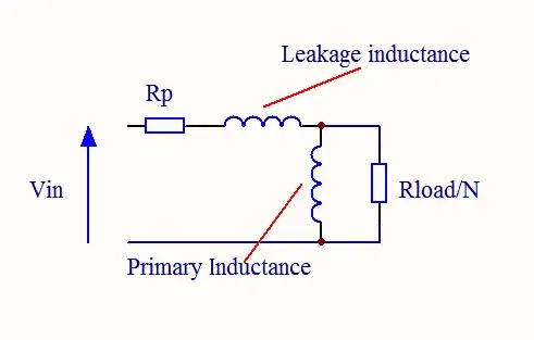
If we consider the equivalent circuit of a transformer below, at low frequencies the response is dominated by the effects of the primary resistance and the primary inductance which form a high-pass filter. The cut-off frequency of this filter is given by \$f_c=\dfrac{R_P}{2\pi.L_P}\$.

Qualitatively, at low frequencies, the primary current is proportional to the input voltage since the primary appears as a resistance. As Olin says in his comment, the secondary voltage is 90° out of phase with the current (it is proportional to the rate of change of current) so we get an overall 90° phase shift.

As the frequency increases, the primary impedance becomes more inductive producing a phase shift in the current. This phase shift subtracts from the original shift and the overall phase shift falls towards zero (but never quite getting there).

If there is a resistive load on the secondary, the leakage inductance eventually comes into effect forming a low-pass filter with the reflected load resistance. This will cause the phase shift to lag further, towards -90°

To take a worked example, I tried to find some specifications for the inductance of mains transformers but manufacturers don't seem to specify this. So I measured a random transformer with a hand-held inductance meter and got 2.5H (hopelessly underestimated since the meter is a cheap audio frequency type). The primary resistance is 47\$\Omega\$. This gives a cutoff frequency of around 3Hz, at which the phase shift will be 45°. At 60Hz, this would have fallen to 2.9°

So that's the "why", but whether this error is significant depends on the application. As others have noted, an opto-isolator may well be a better solution.

Simplified Equivalent Circuit :- Simplified equivalent circuit of a transformer

MikeJ-UK
  • 5,348
  • 15
  • 20