23

I'm using an optocoupler (MOC3021) to sense the On/Off state of an electrial appliance using a microcontroller ATmega16L. How do i go about doing this? My mains supply specs are 230V, 50Hz. How do I design the surrounding circuit and select component values, like the resistors?

EDITED on 13th June 2012 Referring to this schematic Note: This is the first time I'm solving a circuit like this. Please send any helpful feedback. (including things I did wrong or any improvements)

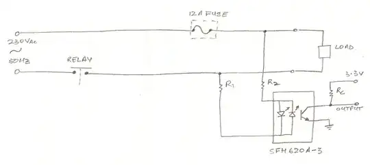
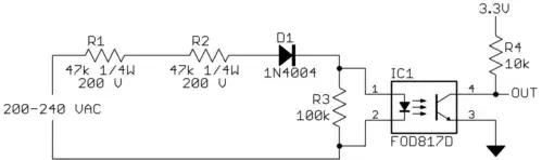
Referring to the above schematic. The idea is to use this circuit to determine whether the load is on or off. The output pin from the optocoupler connects to an external interrupt of the Microcontroller I'm using which is ATmega16L. The interrupt will Monitor the state of the load. After monitoring I can toggle the state of the load using a relay (relay acts as a Control mechanism) which connects to the same microcontroller.

Now, I tried calculating the resistor values for R1, R2 and Rc. Note, microcontroller's VIL(max) = 0.2xVcc = 660mV and VIH(min) = 0.6xVcc = 1.98V and VIH(max) = Vcc+0.5 = 3.8V.

To calculate Rc is quite easy. When the transistor is not conducting the output is high (at 3.3V). When the transistor conducts the output is pulled low. so from microcontroller's point of view, output high means load is switched OFF and output low means load is switched ON.

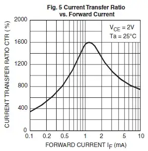
Looking at the datasheet for SFH621A-3, using 34% minimum CTR at IF = 1mA. Therefore, at 1mA input, the output is going to be 340uA. So in order for the microcontroller to detect low voltage from the output of the optocoupler can I use resistor value of 1Kohm? So that the output from the optocoupler will have a voltage of 340mV (which is below VIL(max))

More on this later, been a long day.

EDITED on 15th June 2012

Note: Solving for resistors on the power line (R1 and R2). Please check my calculations and any appropriate feedbacks.

Aim: the aim is to keep the LEDs *ON** for maximum period of time in a 10mS half period (20mS full period of 50Hz). Lets say LEDs have to be ON for 90% of the time, that means LEDs require at least 1mA of current for 90% of the time for that half period which means LEDs will be active for 9mS in a 10mS half period. So, 9mS/10mS = 0.9 * 180(half period) = 162 degrees. This shows the current will be 1mA between 9deg and 171deg (and less than 1mA from 0deg to 9deg and 171deg to 180deg). Did not consider ON time to be 95% as working with whole numbers is neat and 5% doesn't make any difference not in this application at least.

Vpeak-peak = 230V x sqrt(2) = 325V. Taking tolerances into account. Minimum tolerance of 6%. 325 x 0.94 (100-6) x sin(9) = 47.8V

So, R1 ≤ (47.8V - 1.65V) / 1mA = 46.1 Kohms Choosing a value one smaller than 46.1 Kohms of 39 Kohms (e12 series). Now that a smaller value resistance is chosen compared to what was calculated, means current through the diodes will be greater than 1mA.

Calculating new current: ((325V x 110%) - 1.25V)/39 Kohms = 9.1mA (too close to max If of diodes). Coming back to this in a moment [Label - 1x]

First calculate the power ratings of the resistor (considering 39 Kohm) ((230 + 10%)^2) / 39K = 1.64 Watts (too high).

Going back to calculation [Label - 1x] Lets choose two 22 Kohm resistors. Together they add upto 44 Kohm which is quite close 46.1 Kohm(calculated above)

checking power rating of the two resistors combined: ((230 + 10%)^2) / (2 x 22) Kohm = 1.45W. choose 22 Kohm resistors each with 1W power rating.

Now, after all this the initial CTR was 34% which means 1mA in will be 340µA out. But now because of 2x22 Kohm resistors the current will be slightly more on the output. That means higher potential across the pull up resistor Rc. Would there be an issue to get a volt drop below 500mV on the output of the optocoupler??

David Norman
  • 1,475
  • 2
  • 20
  • 31
  • Related question: http://electronics.stackexchange.com/questions/17008/how-can-i-detect-a-power-outage-with-a-microcontroller – m.Alin Jun 01 '12 at 08:18
  • 1
    @Kortuk - Thanks for helping fix the question. I think it's worth it. Cheers! – stevenvh Jun 01 '12 at 12:31
  • @stevenvh, it is always worth it, the way everything had appeared I just had to work to find the signal in the noise :) – Kortuk Jun 01 '12 at 12:43
  • 1
    David, please add some information about yourself on your profile. Like Olin always says that's not for you, that's for us. It helps us to assess your level of knowledge so that we can answer appropriately. – stevenvh Jun 03 '12 at 06:13
  • Re your edit: a 1k resistor will have 340 mV *across* it (Ohm's Law). So the output voltage will still be 3.3 V - 340 mV = 3 V. You have to go lower than VIL(max) if you want the uC to see it as a low. So increase the 1k, for instance to 10k. Then the voltage *across* the resistor will be 3.4 V theoretically, but limited to the power supply, and the output will be 0 V. – stevenvh Jun 13 '12 at 09:43
  • crap, I didn't proof read, I meant 10Kohm for Rc. – David Norman Jun 13 '12 at 09:58
  • Re your edit 2012-06-15 - The 9.1 mA is not too close to max for the LEDs. The [datasheet](http://www.vishay.com/docs/83675/sfh620a.pdf) gives 60 mA as maximum. There's a second reason for using two resistors instead of one, apart from power: [standard 1/4 W resistors](http://www.yageo.com/documents/recent/Leaded-R_MFR_2011.pdf) have a working voltage of only 200 V. Always check this when working with high voltages. A higher output current will cause a larger voltage drop across the pullup resistor, so the output voltage will be lower -> better. – stevenvh Jun 15 '12 at 05:34
  • oh yeah I did look at the working voltage for the resistor. I was thinking the resistor whose specifications are shown below:
    Power Rating: 1 Watt at 70°C Max. RCWV: 200V Max. Overload Voltage: 400V Resistance Tolerance(%): ±5%br/ so two of them in serial will have total voltage of 400V which should be fine
    – David Norman Jun 15 '12 at 05:45
  • man how do I put linebreaks its so annoying – David Norman Jun 15 '12 at 05:46
  • You can't add line breaks or other formatting in comments. It's annoying but they do it on purpose: comments are supposed to be just a brief remark. (The SE staff doesn't like comments at all, but has learned to live with them.) – stevenvh Jun 15 '12 at 07:28
  • Lol i understand – David Norman Jun 15 '12 at 08:21
  • how are my calculations looking? apart from the mistake of max led current – David Norman Jun 15 '12 at 09:49

4 Answers4

30

The MOC3021 is an optocoupler with a triac output. It's used to drive a power triac typically to switch mains operated appliances. Triacs can only be used in AC circuits.

You need an optocoupler with a transistor output, preferably one with two LEDs in antiparallel at the input. The SFH620A is such a part.

enter image description here

The two LEDs in antiparallel ensure that the transistor is activated on both half cycles of the mains. Many optocouplers only have 1 LED, that would work, but give you an output pulse of 10ms in a 20ms period for 50Hz. You would need to place a diode in antiparallel to the input also in that case, to protect the LED from overvoltage when reverse polarized.

Important is CTR or Current Transfer Ratio, which indicates how much output current the transistor will sink for a given LED current. CTR is often not very high, but for the SFH620A we can choose a value of 100% minimum, only that's at 10mA in, at 1mA it's only 34% minimum, so that 1mA in means at least 340\$\mu\$A out.

Let's suppose the output goes to a 5V microcontroller and that you would use the 2k\$\Omega\$ pull-up resistor shown in the diagram. If the transistor is off it won't draw current, except for a small leakage current, 100nA maximum, according to the datasheet. So that will cause a voltage drop of 200\$\mu\$V across the resistor, which is more than safe.

If the transistor is on, and it draws 340\$\mu\$A then the voltage drop across the resistor is only 680mV, and that's way too low to get a low level. We'll have to increase either the resistor's value or the current. Since we had a lot of margin on the leakage current we can safely increase the resistor value to 15k\$\Omega\$ for instance. Then 340\$\mu\$A will give a sufficiently low output voltage. (Theoretically 5.1V voltage drop, but there's only 5V available, so it will go to ground.) The voltage drop because of the leakage current is still well within limits at 1.5mV.

If we want to have a CTR of at least 34% at 1mA we have to use the SFH620A-3.

If this would be controlled from a DC source we would almost be done. Just add R1 in series with the LEDs, R2 will probably not be needed. Then R1 \$\leq\$ (\$V_{IN}\$ - \$V_{LED}\$) / 1mA.

But we have to deal with a 230V AC input signal. At the zero crossings there won't be any current, there's little we can do about that. How can we get at least 1mA for most of the cycle without wasting too much power? This is a trade-off. You can have the 1mA for just the maximum voltage, and that will give you only a small pulse, but you'll waste the least power. Or you can go for 1mA for most of the cycle, but then you'll have more current when the voltage is highest. Let's say we want at least a 9ms pulse in a 10ms half period (50Hz). That means the current has to be 1mA at a 9° phase until 171°. 230V AC is 325V peak, but we have to take a -6% tolerance into account, so that's 306V minimum. 306V \$\times\$ sin(9°) = 48V. R1 \$\leq\$ (48V - 1.65V) / 1mA = 46.2k\$\Omega\$. (The 1.65V is the LED's maximum voltage.) The closest E24 value is 43k\$\Omega\$. Then we have more than 1mA at a 9° phase, but what at the voltage's maximum. For that we have to work with the positive tolerance, max. 10%. Then peak voltage is 230V \$\times\$ \$\sqrt{2}\$ \$\times\$ 110% = 358V. Maximum current is then (358V - 1.25V) / 43k\$\Omega\$ = 8.3mA. (The 1.25V is the LED's nominal voltage). That's well below the optocoupler's limit.

We won't be able to do this with just 1 resistor. It probably can't stand the high voltage, and may have power dissipation problems too, we'll come to that in a minute. Peak voltage across the resistor is 357V. The MFR-25 resistor is rated at max 250V, so we'll need at least 2 of them in series. How about power? 230V+10% in 43k\$\Omega\$ is 1.49W. The MFR-25 is only rated at 1/4W, so two of them won't do. Now you can choose to have more of them in series, but that would have to be at least 6, or choose a higher rated resistor. The MFR1WS (same datasheet) is rated at 1W, so 2 in series will do. Remember that we'll have to divide the resistor value by 2: 21.5k\$\Omega\$, which is not an E24 value. We can choose the closest E24 value an d check our calculations, or choose an E96. Let's do the latter.

That's all, folks. :-)

edit
I suggested in comment that there's a lot more which has to be accounted for, this answer could well be 3 times as long. There's for instance the input leakage current of the AVR's I/O pin, which can be ten times as high as the transistor's. (Don't worry, I checked it, and we're safe.)

Why didn't I choose an optocoupler with Darlington output? They have a much higher CTR.
The main reason is the Darlington's saturation voltage, which is much higher than for a common BJT. For this optocoupler for instance it can be as high as 1V. For the ATmega16L you're using the maximum input voltage for a low level is 0.2 \$\times\$ \$V_{DD}\$, or 0.66V at a 3.3V supply. The 1V is too high. That's the main reason.
Another reason could be that it may not really help. We do have enough output current, it's just that the 1mA input current is so high that we need power resistors for them. Darlingtons don't necessarily solve this if they're also only specified at 1mA. At a 600% CTR we'd get 6mA collector current, but we don't need that. Can't we do anything about the 1mA in? Probably. For the optocoupler I mentioned the Electrical Characteristics only talk about 1mA. There's a graph in the datasheet, fig.5: CTR versus forward current, which shows a CTR of more than 300% at 0.1mA. You have to be careful with these graphs. While tables often give you minimum and/or maximum values, graphs usually give you typical values. You may have 300%, but it may be lower. How much lower? It doesn't say. If you build just one product you can try it, but you can't do that for every optocoupler if you want to run a 10k/year production.
It might work. Say you use 100\$\mu\$A in, and at a relatively safe CTR value of 100% you would have 100\$\mu\$A out. You would have to do the calculations again, but your major advantage will be that the input resistors will only dissipate 150mW, instead of 1.5W. It way be worth it.

stevenvh
  • 145,145
  • 21
  • 455
  • 667
  • @stevenvh Nitpicking a bit - as per datasheet, the CTR for the SFH620A family isn't guaranteed to be 100% at 1mA diode current (you need 10mA) - I believe your 1mA example was hypothetical but it could confuse a newbie. – Adam Lawrence Jun 01 '12 at 15:58
  • @stevenvh Thanks a lot for the solution. you really have put in a lot of effort. ok now the question. What I dont get is this paragraph (quoted from above) [Important is **CTR** or Current Transfer Ratio, which indicates how much output current the transistor will sink for a given LED current. CTR is often not very high, but for the SFH620A we can choose a value of 100% minimum, only that's at 10mA in, at 1mA it's only 34% minimum, so that 1mA in means at least 340μA out.] I don't see how you get 1mA of current. Is that referring to datasheet on Pg3 under "Current Transfer Ratio (Ic/If)"?? – David Norman Jun 01 '12 at 21:40
  • @stevenvh, also instead of using Vcc as 5V can I use Vcc as 3.3V instead so that Vce will be 3.3V. My circuit does not have a supply greater than 3.3V – David Norman Jun 01 '12 at 21:50
  • @DavidNorman The CTR is the ratio of current sourced through the diode current to current sunk by the transistor. In general, you need to drive enough current through the diode to meet whatever the manufacturer specifies in their datasheet in order to have 'guaranteed' CTR, and when you're dealing with optos, it's the minimum CTR that constrains your design. I don't think a slightly-reduced Vce will cause you too much suffering - in my experience it's always the diode current that dominates the CTR. – Adam Lawrence Jun 01 '12 at 21:59
  • Ok another question. At current thought the LED is assumed to be 1mA minimum right? The LED would not light up at 1mA. Also the max current calculated is 8.3mA. Wouldn't LED require atlest 12mA to ensure it turns ON? 1mA and 8.3mA does make sense to me. I think I'm wrong but thats what i understood – David Norman Jun 01 '12 at 22:14
  • There is another thing I dont get. you calculated 340uA on the output using CTR right? Now if transistor conducts, wouldn't there be **more** current flowing through the resistor labelled 2K? – David Norman Jun 01 '12 at 23:48
  • @David - The datasheet doesn't talk about currents less than 1mA, so I wanted to be safe and chose that. It's a low current, but it's enough for the 340uA at the other side. Your last question is a common misconception about transistors used as a switch. A real switch doesn't limit the current, but a transistor does. It can't draw more current than the LED current and CTR define. Even if the load will allow it. So you choose collector current high enough, so that the load becomes the limiting factor, and the transistor goes into saturation. – stevenvh Jun 02 '12 at 05:15
  • @David - Sure, 3.3V also works. The same 15k can be used, you could use 10k as the lower limit: 10k \$times\$ 340uA is a 3.4V drop across the resistor. If your PS is 3.3V it can't go that low, so it will stop at ground (plus a couple 100mV, the saturation voltage of the transistor). Always choose the resistor low enough so that it is the limiting factor in the current, not the transistor. – stevenvh Jun 02 '12 at 05:43
  • @stevenvh - sweeeet. ok the paragraph starting with "But we have to deal with a 230V AC input signal." The two resistors you calculated the value for are resistors R1 and R2 on the diagram above right? I always wondered for this configuration if I put R1 and R2 beside each other on the top line instead of distributing them one on each line. Would that make any difference? Say top line is 'Live' and bottom is 'Neutral'. so if no resistors are present on the Neutral line and during the negative phase the current will be going directly into the diodes as compared to two resistors on Live line? – David Norman Jun 02 '12 at 06:05
  • @David - Oops. "Always choose the resistor **high** enough". Sorry! – stevenvh Jun 02 '12 at 06:09
  • 2
    @David - The order of components in series doesn't matter, the voltages across the different components will always be the same, like 1.25V for the LED, even if connected directly to the mains phase. It's true that touching them when they're at the neutral's side would be less dangerous, but I don't think that's a required feature. Besides, when you use a power plug to connect to the mains **you're not sure which is the phase and which the neutral. Never touch a wire supposing it's the neutral!** It could be the last error you make. – stevenvh Jun 02 '12 at 15:14
  • ok great. I feel so dumb. This is the first time I'm dealing with electrical project. Anyway, I cant thank you enough stevenvh. Also I will try to do my own calculation from what I've learnt from this thread. Is it fine if I can post my working on this tread for you to take a glance? is there a way to do that? – David Norman Jun 03 '12 at 05:53
  • @David - hey, that's alright, we all have to learn. About posting your work. Don't do it here. You can't show images and they don't like to much person-to-person conversation here (you may have seen a hint to that already). I would add it as an update to your question. It will bump the list and get attention, and maybe new answers which shine a different light on it. Success! – stevenvh Jun 03 '12 at 06:10
  • @stevenvh - great I'll do that and hey thanks a ton for helping me out. Your explanations are awesome and I really appreciate for what you've done. – David Norman Jun 04 '12 at 00:37
  • A concern, if resistors R1 and R2 are connected parallel to the load, wouldn't there be a 230V drop across the anti-parallel LEDs? – David Norman Jun 13 '12 at 07:33
  • @David - *A diode fixes its own voltage*, like 1.2 V for the LED. In both directions because of the antiparallel. So the remaining voltage, the 324 V peak, will automatically go to the resistors. That's why you need a couple of them in series, common resistors can't handle that voltage. If the second LED weren't there then the reverse voltage would indeed be completely over the LED since reverse it doesn't have that fixed voltage. This would destroy your optocoupler, probably explode. – stevenvh Jun 13 '12 at 07:41
  • @stevenvh - I'm referring to paragraph starting with _But we have to deal with a 230V AC input signal._ Is there a reason why you 1mA for a 9ms pulse in a 10ms half period? Also how did you get 9degrees? – David Norman Jun 14 '12 at 03:51
  • The 9 ms pulse is just an example, you can make it shorter if you wish. A half cycle of 180° is 10 ms, so 9 ms is 162°, that's 9° cut off left, and 9° cut off right. Even outside that you will have current, but it will be less than 1 mA. Since we have this 10k pull-up resistor the output voltage will be seen as a low by the microcontroller for a longer time. The *230V AC* refers more to the AC than to the 230 V. – stevenvh Jun 14 '12 at 04:25
  • Oh I see, so if I choose to have a 5degree phase, means the current will stay at 1mA from 5degrees until 175degrees. that gives the microcontroller even longer time to be seen as a low logic. And the current is below 1mA from '0deg to 5deg' and '175deg to 180deg'. Am I thinking in the right direction? – David Norman Jun 14 '12 at 21:54
  • @David - Completely correct. There will always be a point, at the actual zero-crossing, where the output goes high, so it's a bit pointless to stretch the pulse too wide. The average current from the 230V will rise too: to get 1mA at 5° (which is a lower voltage) you'll have to decrease the resistor values, so they have to be higher power to cope with the higher (peak) current. If you go for a 45°-125° pulse (5ms) then you have to sample just twice in a 10ms half cycle to be sure not to miss the low level. – stevenvh Jun 15 '12 at 04:51
  • awesome, how are my calculations looking? (I edited the question again). Do you notice any errors? I tried to make sense of it all before getting down to calculating the resistor values. – David Norman Jun 15 '12 at 05:27
7

In my other answer I explained why I didn't use a Darlington optocoupler there: the main reason is the Darlington's saturation voltage, which is much higher than for a common BJT, it can be as high as 1 V. For the ATmega16L you're using the maximum input voltage for a low level is 0.2 × VDD, or 0.66 V at a 3.3 V supply. The 1 V is too high.

But it's not a thing which can't be fixed, it takes just a couple of extra components. At the same time we'll do something about the 1 mA input current as well.

To start with the input current, we had to use 1 mA because the datasheet didn't mention anything lower, and then you can try things, but you're on your own, there are no guarantees. The datasheet for the FOD816, however, has an interesting graph.

enter image description here

That's the one. This one does give CTR for input currents as low as 100 µA, and it's even high: 350 % (remember this is a Darlington). But you have to be careful with these graphs. While tables will often give you minimum or maximum values this kind of graphs will give you typical values, unless indicated otherwise. So what's minimum? We don't know, but 100 % is safe. Let's go for even more safety and assume a CTR of 50 %. So for 100 µA in we'd get 50 µA out. Let's see if that's enough.

This is the modified output stage. U1's transistor is the photo-Darlington, sourcing the 50 µA when on. Let's choose 10 µA for R4, so its value will be 0.6 V/10 µA = 60 kΩ. I'll come back to the function of R4 later.

enter image description here

Then we have 40 µA remaining for T1's base current. If we pick a BC857A for that we have an \$H_{FE}\$ of 125 minimum, so our collector current is minimum 5 mA. An R5 of minimum 660 Ω is enough to make the output low. Since we're driving a high-impedance microcontroller input we don't need the 5 mA, and might as well choose 15 kΩ, so that limits the current to 220 µA. The 1 µA input leakage of the controller's port will only cause a 15 mV drop, so that's OK.

What's the function of R3? It's normally used to limit the base current, but doesn't the Darlington do this already? Yes, it does, but the value can go pretty high. In my other answer I calculated that the peak LED current could go as high as 8.3 mA, that will become 830 µA in our low power version. We calculated with a safe CTR value of 50 %, but typically it will be 350 %, and maximum maybe even higher. 830 µA \$\times\$ 350 = 290 mA, which is too much for that poor BC857A. So we'll limit that to 100 µA by choosing a 15 kΩ value for R3.

R4 still needs some explanation. Suppose we omit it. Then all the Darlington's current goes to T1. When off the FOD816's leakage current (called "dark current" in the datasheet) can be as high as 1 µA. T1 will amplify that to 250 µA maximum worst case, which is enough to drop 3.3 V across R5. So the output may be permanently low.
We chose a value of 60 kΩ for R4. Then as long as the voltage drop across it is less than 0.6 V all the Darlington's current will go through R4, and none through T1, because the minimum base-emitter voltage isn't reached. That was at 10 µA. So the 1 µA dark current will only cause a 60 mV drop, and no base current.

We have values for all our components, the only thing remaining is to increase the input resistors to 220 kΩ each. You can use 1/4 W resistors for that.

stevenvh
  • 145,145
  • 21
  • 455
  • 667
  • Thanks steve. unfortunately i cant post any more questions as I'm blocked by Kev(moderator) which sucks. I will get back to my project from next week. Been working long hrs lately. Regards – David Norman Jun 12 '12 at 01:09
  • You could say R4 provides a threshold value the current has to exceed to get T1 into conduction. – The Resistance Dec 14 '13 at 09:53
3

To figure the parameters of the circuit, start with what you need at the output and work backwards. 10 kΩ is a good value for the pullup on the output. Unless you have unusual requirements, like battery operation where low power is important, 10 kΩ is a good tradeoff between low enough to pull the line solidly high against leakage and reasonable noise, but not so low as to require too much current.

When the output transistor in the opto turns on, it will put at most 3.3 V accross Rc. 3.3 V / 10 kΩ = 330 µA, which is the minimum current the transistor must be able to sink. You want some extra so that the line is held solidly low when it is supposed to be low. I'd say at minimum it should be able to sink 500 µA, but I'd use 1 mA unless you have a particular reason to cut it close.

Now that we know that the output has to sink 1 mA, we look in the datasheet of the opto to see how we need to drive it to get that 1 mA out. You are using the "-3" variant of this part, which according to the first page of the datasheet has a minimum guaranteed current transfer ratio of 100%. That means that the transistor can sink at least as much current as you put thru one of the LEDs. However, note the little "±10 mA" above the CTR specs. What this is really saying is that if you put 10 mA thru the LEDs, then the transistor will be able to sink at least 10 mA. It doesn't actually promise anything at any other input current.

Looking thru the datasheet more, you find additional information at the top of page 3. Here they actually show the CTR for 1 mA input. Note that now it's only guaranteed to be 34%. That means to get the 1 mA output sink capability, you have to drive the LEDs with 1 mA / 34% = 2.9 mA, so let's aim for 3 mA absolute minimum.

You say the voltage that has to be sensed is 230 V AC. Since that is a sine, it will have peaks of 325 V. The output signal of the opto is going into a micro, so there is no need for it to be a steady signal when power is on. In fact, it's a good idea for the micro to be able to ride out momentary interruptions and glitches. I'd probably keep a counter that is decremented every ms when the signal is off and reset to something like 50 when on. That means you have to see no signal for 50 ms to declare that power is off. All that is needed is a little blip at the peak of the line cycle and this system will work fine. Note that line cycle peaks occur every 10 ms with 50 Hz power.

So let's see where we're at. We want to have at least 3 mA flow thru the LEDs when the power voltage is 325 V. The LEDs will drop up to 1.65 V (top of bottom table on page 2), and this should still work at the lowest reasonable power line voltage. Let's aim for being able to detect 200 VAC minimum, which is 283 V peak, and 281 V after the LED drop. 281 V / 3 mA = 94 kΩ. In theory, that's all that is needed in series with the LEDs to trigger the output at least a little bit once per power peak.

In practise it's a good idea to add some margin. You want the output to be asserted for a reasonable finite fraction of each half-cycle, not just guaranteed to be on for a little blip. Given all that, I'd roughly halve the resistor to 47 kΩ. That will solidly turn on the output for all reasonable conditions with significant margin.

You might think that's all you need to do, but wait, there's more. Think what will happen at high line voltage, like 240 V. The peaks are 340 V, which would cause 7.2 mA thru the LEDs. You have to check the maximum allowed LED current, which is 60 mA, so that's OK. However, consider the power dissipation in the resistor. If we say the worst case line voltage is 240 V, then the power going into the resistor (ignoring the LED voltage drop) is (240 V)2 / 47 kΩ = 1.23 W. That should be at least a "2 W" resistor then, and it will get noticeably warm.

Another issue is that the voltage rating of the resistor needs to be considered. It needs to be able to withstand the 340 V peaks, so overall you need a 47 kΩ resistor rated for 2 W and 400 V. Those can be found, but it might be simpler all around to use several resistors in series. That spreads out the peak voltage and the power dissipation among the series resistors. Four 12 kΩ resistor would do this and will only dissipate 300 mW and see 85 V each. That will be easier to find and cheaper than a single resistor unless this is a volume product where you can buy things in large quantity. So the answer to the question as asked is to put four ordinary 12 kΩ 1/2 Watt resistors in series with the LEDs.

Note that these don't need to be split up on each side of the opto as you show R1 and R2. There only needs to be a single resistance in series with the LEDs somewhere. Since this resistance happens to be made up of four individual resistors in this case, you can split them up any way you like to make things work out best mechanically on the high voltage side of the circuit. Preferably they would be end to end to maximize the creapage path for the high voltage and to spread out the heat.

However, I don't really like this optocoupler for this application since it has such low current transfer ratio, which forces us to provide a lot of LED current, which causes a lot of power to be consumed in the resistor. For this sort of application where high current transfer ratio is useful and speed doesn't matter much, I like the cheap and available FOD817. The D versions of this part have a guaranteed CTR of 3x at 5 mA. They don't say exactly what you get a 1 mA, but it's a pretty safe bet the output can sink at least 1 mA with 1 mA in.

The FOD817 has a single LED, but that is easy to deal with (The FOD814 has back to back LEDs, but is less available and doesn't come in some of the higher gain variants). Using the 50 ms scheme described above, it's no problem if you get a pulse once per line cycle, which is every 20 ms. Put a diode in series with the LED in addition to the resistors, and a high-value resistor accross the LED to make sure it doesn't see high reverse voltage due to a little bit of diode leakage. 100 kΩ is fine, and is high enough for its current to be irrelevant to our other calculations. Another advantage of this is that not only do you get lower power dissipation due to requiring less LED current, but you get another factor of two reduction in power due to the LED only being driven in one direction. A total series resistance of 100 kΩ or so will still give you plenty of current headroom at the power line peaks, but will dissipate less than 300 mW total due to the lower current and being on only half the time.

So here is my final answer:

Olin Lathrop
  • 310,974
  • 36
  • 428
  • 915
  • Hey Olin. I am considering if I can get away with an `SFH620A-3` and only two `1/4W` `250V` resistors. For `R1=R2=47K` input resistors I get `2.45mA` at 230VAC _average_. For a little bit higher output resistor e.g. 15K this should work, right? Or do I need to calculate using peak voltage? And account for tolerances. – Vorac Nov 16 '15 at 18:38
  • Oh, the power doesn't work out. And those are the components I have on hand. Can it really not be done with those component types and minimum component count? – Vorac Nov 16 '15 at 18:41
  • Last comment, I promise. I expanded the above comments into a [question](http://electronics.stackexchange.com/questions/201238/would-this-lazy-zero-cross-detector-work). – Vorac Nov 17 '15 at 10:14
  • @Vorac: It's unclear what you're asking. I described how to do the calculations in detail in my answer. The resistors must be able to handle the average power they dissipate, but the peak voltage across them. – Olin Lathrop Nov 17 '15 at 11:29
-2

If you're looking for a very high CTR for this type of application, look at the Liteon LTV-8xxx series. 600% min. at 1mA IF.

Nick Alexeev
  • 37,739
  • 17
  • 97
  • 230
  • Welcome to EE.SE! If you're referencing a part, please have links to datasheets in your post. – Nick Alexeev Jan 17 '14 at 22:57
  • Do you have some reason to believe that a higher CTR would help the OP? If so, could you explain that please? If not, then this information should be added as a comment to the question rather than as an answer. – Joe Hass Jan 17 '14 at 22:58
  • Nick, will add links as suggested next time. – GoneCamping Jan 20 '14 at 14:23
  • Joe, higher CTR's give you the chance to reduce the AC limiting resistor current for a given output current, thereby reducing the wattage (and associated costs.) – GoneCamping Jan 20 '14 at 14:24