8

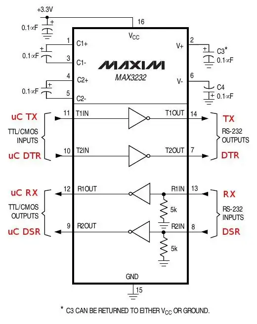
We have a product which is using a MAX3232C for interfacing to a PC. Its RS-232 RX line is tied to the MAX3232's R1IN pin and its TX line to T1OUT:

circuit schematic

The problem we are having appears to be some kind of crosstalk between the RX and TX lines.

scope image showing crosstalk effect

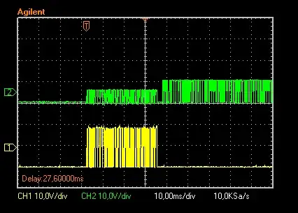
This scope image is showing exactly the same bit stream received on RX (yellow) coming out of TX (green), but with a little distortion and a smaller amplitude (the TX bit stream following the "crosstalk packet" is just the expected answer packet from the device).

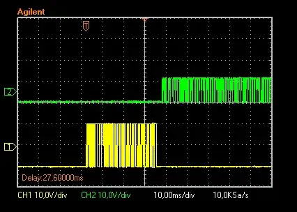
The baud rate is rather low (9600 bps), so we wouldn't expect to see that due to PCB design issues. To rule out a PCB problem, we exchanged the MAX3232C from Texas Instruments for a pin-compatible device from ST Microelectronics, an ST3232C, and the problem vanished:

scope image showing no crosstalk effect after IC exchange

That said, has anyone ever experienced a similar problem with MAX3232? Can anyone imagine other possible causes for the problem other than a faulty I.C.? Just for the record, we observed the same problem with other units also using MAX3232C devices.

Claudio
  • 396
  • 5
  • 13
  • What points exactly in your schematic are the scope traces showing? Your description implies you are looking at the logic level side, but the voltage levels are way too high for that. Be clear about what you are measuring and who is sending to whom. – Olin Lathrop May 30 '12 at 19:02
  • @OlinLathrop, the yellow trace was taken at the RX mark (MAX3232C pin 13) and the green one at the TX mark (pin 14). – Claudio May 30 '12 at 19:03
  • 2
    If you encounter this problem, then you are most likely dealing with a Chinese-made counterfeit MAX3232 chip. I just went through this same ordeal, it is apparently very wide-spread. –  Nov 13 '15 at 16:59

1 Answers1

3

I would guess that it could be lack of supply stiffness with the MAX device.
Are the pump caps 0.1 uF as shown.

And what cap is on the 3V3 rail and how far away is it from the IC.

If the power supply is not stiff enough either because the "pump" lacks energy or the source rail is noisy then something like you are seeing could happen.

Pin 2 and pin 6 (V+/V-) should have some ripple at the pump frequency but no signal frequency noise to speak of.

What supply voltage are you actually using?

What is the drive voltage on the low voltage side?

It may well not matter but the TI data sheet in figure 4 bottom of page 7 shows differing cap values for different supply voltages.

The Maxim data sheet shows the same values in table 2 at the top of page 12. Maxim say these are minimum capacitor values. TI says that the same values are typical values.

Note that the spurious output is unipolar - it's not that it's low - the scope ground is at half waveform height and the proper signal is ~+/- 5V, as it should be, but in spurious mode it's -5/0V. This implies that the + side pump isn't working or that Murphy has proclaimed a bank holiday. I'd start by checking voltages on C3 & C4, supply capacitor size and correct capacitor values.

Russell McMahon
  • 147,325
  • 18
  • 210
  • 386
  • McMahon, the 3V3 supply seems OK, and the caps are all 0.1uF and close to the IC (everything SMD). – Claudio May 30 '12 at 20:03
  • The 3V3 rail is fed by a low-noise and low-dropout 3V3 regulator (LP3982) with a 47uF cap at its output. Its allows caps over 10uF as long as their ESR is lower than 0.5 ohm. I have to check that out since I didn't design the hardware, but on the scope the 3V3 line looks pretty stable. I'll check your suggestions and get back here.. thanks! – Claudio May 30 '12 at 20:29
  • @RusselMcMahon, although the "crosstalk signal" is mostly negative, if there was a problem with the positive pump, the proper answer packet shouldn't come out right either, and on the scope it properly swings from +/- 5V, don't you agree? – Claudio May 31 '12 at 13:40
  • 1
    One thing which is making my colleague believe this is a problem with this batch of ICs is that the **ST3232** parts do not show the crosstalk effect, and neither another **MAX3232I** part he also tried in exchange for the original **MAX3232C**. – Claudio May 31 '12 at 13:57
  • @Claudio - No. That's logicla and possibl. MAYBE even probable. But not certain. eg the data signal driving the IC may cause internal conduction paths and help drive the pumps. – Russell McMahon May 31 '12 at 14:25
  • 1
    @RusselMcMahon, sorry for the long "silence", but I was very involved in another firmware project and this question I raised here was indeed more related to my colleague's problem (he's not much into online communities, so I couldn't get him to keep tracking down the cause so we would get to the end of this). In the end he just exchanged the MAX3232C part for both a MAX3232I and a ST3232 and was happy about them not being faulty :P, but I still want to get my hands on the original MAX3232C and isolate it along with the strict minimum components required to test it (more on next comment...) – Claudio Jun 18 '12 at 21:50
  • 1
    (continuing...) One interesting thing to note, as you can see on the first scope image, is that the input on this MAX3232C seems to act as a load, clearly attenuating the source signal (yellow trace) if you compare it to the next scope image, which shows the ST3232 part with no attenuation on the input signal. Another thing worth mentioning is the crosstalk on the MAX3232C output (pin 14, marked with TX) also appeared when the input signal was applied to the other channel's input (pin 8, marked with DSR). – Claudio Jun 18 '12 at 22:01