0

When I toggle a push button switch on and off, instead of getting a pure on/off continuity levels I sometimes get "transitional" values. I need it to be purely on/off with nothing in between. What components do I need to add to the switch to make that happen?

There is +5 V being applied at what is labeled "TIP".

enter image description here

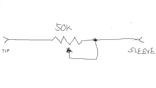
Here is am drawing of the original circuit I am trying to replace:

enter image description here

Null
  • 7,448
  • 17
  • 36
  • 48
Brak
  • 1
  • 2
  • Can you tell us what the pushbutton is connected to? – Barry Sep 14 '17 at 02:23
  • Thank you everyone for all the helpful responses. I have uploaded a picture (please excuse the crudeness - I'm not good at drawing with a mouse lol) showing the circuit as it is currently setup. So in the circuit there is +5v being applied to what is labeled as "IN". So each button push is to provide a different return voltage level to the device it is plugged into. – Brak Sep 14 '17 at 16:25
  • @Barry This is for a musical device. The device has a T/S jack for connecitng what is known as a Continuous Controller. Usually a regular 50k or 100k ohm pot is connected, allowing the user to rotate the knob to get various CC values ranging from 0 (full resistance) to 127 (no resistance). I want to, instead of using a pot to "dial in" the values I need, to use a series of push buttons (with resistors) that will give specific values. So everything works perfect.... except for the bouncing (thank you all for giving me the term) giving "transitional values". – Brak Sep 14 '17 at 16:29
  • too bad you didn't start with this in the question, we would have wasted less time. I wonder if it was to simulate a flute, a trumpet, organ. The key quality is crucial just like a keyboard. – Tony Stewart EE75 Sep 14 '17 at 21:22
  • @Tony, I provided this information long before we went down the rabbit hole we did. :) I guess it didn't show up for you until now. In fact I posted that comment before I edited my post to include my attempt at a drawing of the circuit. – Brak Sep 15 '17 at 04:22
  • On a different forum, in which I asked this same question, a poster clarified my question in a very awesome way. He stated "the circuit is a fully-passive, switch variable resistor on a remote control style hand-held cable terminated into a 2-pole audio connector." That description nails it, except for maybe the "hand held" part. Hopefully this additional info helps. – Brak Sep 17 '17 at 03:42

3 Answers3

1

Mechanical switch contacts "bounce" both when making and when breaking. Bounce is when the contacts make partial, higher resistance contact or bang into each other repeatedly and very quickly. It is common for contacts to make and break 5 or 10 or even 100 times in a few milliseconds. Depending on the circuit the switch is driving, this can be taken as an intermediate voltage or as 100 really fast clock pulses.

The standard way to fix this is to "de-bounce" the switch with an electronic circuit. Two common methods are 1) any one of a group of circuits that essentially act as a lowpass filter; or 2) have the switch input clock a flipflop. Once a "1" is clocked into the flipflop, multiple successive clocks have no affect. With this method, you have to reset the flipflop before it will respond to another button press.

AnalogKid
  • 16,865
  • 1
  • 13
  • 25
0

All you need is cap. such that the RC=T exceeds the bounce time using the large internal pullup R.

The contact closure gives a low RC attack time and the release a slow decay time to act as a Sample and hold for as many milliseconds to cover your transitional time.

Logic and software can also do the same thing with edge detection with a timeout.

After new info

But if you introduce a series string of binary weighted R's, the the MSB R weighted value will swamp the value of all the others.

The only solution then is to use software averaging and choose analog thresholds to discriminate which combination of switches are active. You then have to deglitch by averaging or look for successive values in a 5% window of full scale for a duration > max transitional time.
Tony Stewart EE75
  • 1
  • 3
  • 54
  • 182
  • I like the idea of using a cap to solve the problem, it seems to be the easiest method to apply. So my question is (based on the current circuit I posted) what value caps (and maybe resistors) should I add? – Brak Sep 14 '17 at 16:26
  • if T=1ms bounce interval then T=0.1uf*10k or 0.01uF*100k, if T interval is more like 100ms then increase either R or C such product T is 100x. Bounce transition time could be 5ms with chatter interval 1ms, then you only need >=1ms add some for aging margin. – Tony Stewart EE75 Sep 14 '17 at 17:11
  • Stewart, Since each switch is connected to a different resistance value (switch 1 has 0, switch 2 has 10, switch 3 has 20, switch 4 has 30) would each switch have a different value? Also for switch 1, which has 0 resistance... what value cap would be used there as anything * 0 is 0. Or do I use the value of all the resistors tied together (40) for the calculation and use that same value for all the switches. Please clarify. – Brak Sep 14 '17 at 17:16
  • that wont work. Define your min. transition time interval between valid states and the max. time during invalid transition please – Tony Stewart EE75 Sep 14 '17 at 17:20
  • I don't think I have a way of timing it to that level of resolution; it happens pretty fast. So I would clearly need to fine tune the value via trial and error. Using a metronome I need to be able to switch on/off 1.3 time per second - so lets say 300ms for the calculations for a starting point. – Brak Sep 14 '17 at 18:04
  • But I still don't understand what resistance value to use. – Brak Sep 14 '17 at 18:05
  • What does "MSB R weighted" mean? – Brak Sep 14 '17 at 18:07
  • I don't have a software option - I need to solve this via hardware. As I explained to Barry, the device I am using this with is typically used with a 50k or 100k pot. So I am trying to use a series of push buttons to act like a pot with select values. The circuit I have above works perfect, except for the switch bounce. – Brak Sep 14 '17 at 18:12
  • Also, what should the voltage value be for the cap? Also, should it be a fixed or polarized cap? – Brak Sep 14 '17 at 18:23
  • In binary weighted R's 1-2-4-8-16..., most significant bit has the biggest step or MSB weight. I can't help seeing new information you are leaving out in the question. Like time durations, R values and sequential timing and results like this make all the difference. No answer is possible yet. – Tony Stewart EE75 Sep 14 '17 at 18:28
  • okay.. I googled MSB - as I didn't know what that acronym meant (hence me asking). So with talking about binaries, most-significan-bits, and software; I am wondering if we are talking about the same thing - hence the confusion. I am working with analog. I just need to make a bunch of push buttons and resistors working together to act like a potentiometer. – Brak Sep 14 '17 at 18:38
  • So to simplify the question maybe: what components (and their values) do I need to add to my circuit to stop the bouncing (assuming the timing value of the bouncing is 300ms)? And of course where/how to I add them? – Brak Sep 14 '17 at 18:39
  • not possible , your design needs more effort to answer all my questions including potential switch timing , valid response times etc. and why you changed to binary weight is not explained nor the quality of switches. So too many issues unrelated to this simple question. – Tony Stewart EE75 Sep 14 '17 at 18:56
  • Maybe I am not understanding your questions. :( What is "binary weight"? Can't explain why I "changed to binary weight" if I don't know what that means. – Brak Sep 14 '17 at 21:16
  • To try to explain it by using a related example that might be more clear: Instead of using a pot to select 0-10 I want to replace the pot with switches to select those values individually: so I can go from 2 to 9 to 3 to 6 without having to guess where I am on the pot nor getting the intervening values. – Brak Sep 14 '17 at 21:18
0

The issue you are facing (or more accurately the solution) is called 'debouncing'. Google it and you will find answers.

When a physical switch closes, and applies a voltage that goes from (let's say) ground to 10V (or whatever), at first there is intermittent conduction. Think of it as microscopic sparking, until a solid circuit is formed. Then it is solid at 10V.

usually, a capacitor (with or without a resistor) across it will do the trick.

eSurfsnake
  • 340
  • 2
  • 7
  • I like the idea of using a cap to solve the problem, it seems to be the easiest method to apply. So my question is (based on the current circuit I posted) what value caps (and maybe resistors) should I add? – Brak Sep 14 '17 at 16:26