14

I am using a very sensitive transimpedance amplifier on a 3m long cable to a photodiode. Signal levels are about 70 nA - 700 nA. Bumping into the cable causes a large voltage spike on the output of the amplifier. The insulating material is FEP.

Could this be the piezoelectric effect in the cable insulaton?

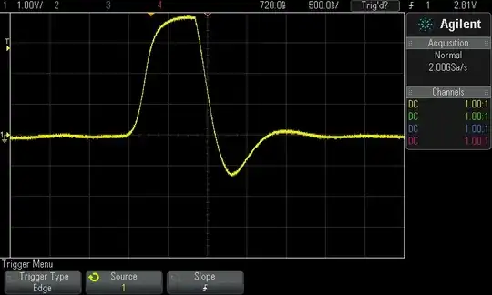
Edit: Here's a typical voltage spike. This happens when I bend, shake or tap the cable. Voltage spike when bumping the cable

JRE
  • 67,678
  • 8
  • 104
  • 179
kva
  • 440
  • 3
  • 11
  • 4
    No. But it could be electromagnetic effect, as a charge carrier moving inside of some magnetic field will get a current induced. Or just check your connections and contacts. They migh be broken and get affected by mechanical impact.. – Eugene Sh. Sep 13 '17 at 13:52
  • 1
    Not piezoelectric, just plain old microphony. – Finbarr Sep 13 '17 at 13:59
  • 6
    @Fin: That doesn't make any sense. I agree it's not piezo, but think about what mircophony means. One cause of microphony *is* piezo effects on things like certain ceramics of capacitors. Otherwise, "microphony" would require some kind of induction. You'd have to explain where that comes from. – Olin Lathrop Sep 13 '17 at 14:09
  • Read https://en.wikipedia.org/wiki/Microphonics https://www.researchgate.net/publication/245488544_Microphony_of_coaxial_cables https://www.atlascables.com/design-construction.html – Uwe Sep 13 '17 at 14:10
  • 1
    @OlinLathrop Microphony can also be due to movement of charges due to vibrations - no induction required – Joren Vaes Sep 13 '17 at 14:25
  • 4
    @Joren: That would be a capacitive effect, not a piezoelectric effect. – Olin Lathrop Sep 13 '17 at 14:27
  • 1
    @OlinLathrop Yes, but I never claimed it was a piezoelectric effect. I was giving an counterexample to your claim "Otherwise, "microphony" would require some kind of induction. " I interpreted it as you claiming that microphonics are either piezoelectric or inductive. – Joren Vaes Sep 13 '17 at 14:37
  • 1
    Photodiode's on the ends of cables are often an issue. You will also lose BW due to cable capacitance. And chance to put an amp (TIA) with the photodiode and let it drive the cable? – George Herold Sep 13 '17 at 14:57
  • Possibly related: *[EEVblog #162 – Oscilloscope Probe Shock](https://www.eevblog.com/2011/04/12/eevblog-162-oscilloscope-probe-shock/)*. I think there was a followup that partly or completely turned it around, but I couldn't locate it. ([List of all videos.](http://www.eevblog.org/video/)) – Peter Mortensen Sep 13 '17 at 17:00
  • When I worked with a mfgr of digital o'scopes back in the 80s, one way of creating a test pulse when no signal source was available was to simply hook up a co-ax cable to the BNC input and whack it on the benchtop. Voila! – c-squared Sep 15 '17 at 19:46

6 Answers6

13

Triboelectric effect probably.

You can find cable made for musical instruments that is screened with a low resistance carbon impregnated layer (They call it semi conducting!) between the screen and the insulation of the centre conductor, this is helpful when dealing with high Z sources as it minimises the noise due to movement.

Dan Mills
  • 17,266
  • 1
  • 20
  • 38
9

Adding to Jack's answer:

Triboelectric effects are just like every day static electricity: rubbing dielectrics together rips some electrons out and creates charge.

This creates a current (i=dq/dt)/

How this will affect your measurement is proportional to the impedance of the circuit driving the cable. The error voltage created is Z*i according to ohm's law. If the cable is driven from the low impedance output of an amplifier, then the effect will usually not matter at all.

But you are measuring tiny photodiode currents, so here it matters.

There is another effect: your coax is a capacitor. If it is charged to a DC voltage (not 0V) then bending it will modify its capacitance. Since the charge inside the cable's capacitance is constant, changing the capacitance changes the voltage. Again, this only matters in a high-impedance setting... like yours.

Solutions:

  • Everything Jack said

...and the obvious one, although not always possible:

  • Put the amplifier next to the photodiode and have its low-impedance output drive the cable.

If you want non-triboelectric coax, the keywords you have to google are "low noise coaxial cable". This is a type of coax with a graphite/carbon based resistive layer between the insulation layers, which dissipates any charge created by rubbing. However, they are hard to find and expensive. They are used in electrocardiograms, or for vibration measurement using piezo sensors, for example.

I also second the use of stage microphone cable: musicians like cables which don't produce a THUMP in the speakers when someone steps on the cable. If you walk in any music/guitar shop and ask for such cable, the sales person will know what you're talking about. They may not know about the physics involved, but they will know about clients returning cables because thy're microphonic...

These cables usually have a cotton filler around the wires, which does not generate charge when bent.

I use balanced stage microphone cable for audio measurements: they're cheap, easily available, and work very well. No need for fancy audiophile stuff.

If you want coax, try guitar cable. They're designed for the same setting: tiny signals, lots of spastic movement, high-Z setting... These won't be specified for HF impedance though.
bobflux
  • 70,433
  • 3
  • 83
  • 203
  • I need a shielded cable containing about 12 twisted pairs. I am using 3 of these [rs232 cables](http://www.belden.com/techdatas/metric/89504.pdf?ip=false) Audio cables would be too bulky for my application. Do higher density cables exist with this special coating? – kva Sep 14 '17 at 08:07
  • No idea. The closest I got was http://www.femto.de/en/products/accessories/low-noise-cable.html but... they're very expensive. Although... why not use Flex PCB? or FFC/FPC jumpers? In a Flex, all the layers are glued together, so they won't rub, there should be no charge buildup... Note this is just a hunch, but maybe worth a try... – bobflux Sep 14 '17 at 09:19
  • @kva -- a microphone "snake" cable sounds like what you're after – ThreePhaseEel Sep 15 '17 at 23:53
  • @threephaseeesl I looked it up. Seems like I need multi-conductor broadcast cables of some sort. – kva Sep 17 '17 at 06:57
  • http://www.mogamicable.com/category/bulk/snake/ this one specifies microphony "50mV into 50kOhm if you step on it" probably too much for your application though – bobflux Sep 17 '17 at 12:01
3

This sounds like microphonic effects in the cable. It arises from several sources, some of which have been mentioned in other answers, including

  • Surface charge building up on the insulators, then being discharged when the cable bends
  • Triboelectric effects (i.e. friction)
  • Piezoelectric effects (in the insulator, not the copper)

It could also be capacitive or inductive pick-up. Though this is less likely if you already have good quality shielded cable with a grounded shield.

Common solutions include:

  • Cables with slightly conductive packing material which bleeds out any accumulated charge
  • Cables with different insulator materials which are less susceptible to charge build up or triboelectric/piezoelectric effects.
  • Stiffer cables which are less likely to bend and pick up noise as a result.
  • Larger diameter cables with lots of filler, which reduce the bending on individual cores.
  • Running cables where they are not likely to be bumped/disturbed.
  • Covering or protecting cables with foam to avoid acoustic pick-up from the environment.
  • Nailing or otherwise fixing them down so they can't be bumped/moved, though be careful not to crush or damage them.

Cables designed for on-stage audio use might be good here, as they are often non-microphonic. There is a lot of overpriced garbage in the audiophile market, but there are also some nice products which - though vastly overengineered for audio use - are great for precision lab equipment.

Jack B
  • 12,167
  • 1
  • 27
  • 46
  • We use the cables for equipment verification. Equipment is stored in large racks with cables running in front. It is possible that someone bumps into them. Perhaps during critical tests we should warn people to not touch the cables? For long term tests cables could be secured using zipties to the chassis I suppose. – kva Sep 14 '17 at 14:20
2

Copper doesn't exhibit any appreciable piezoelectric effect.

What is probably happening is that small charges are getting moved around on the outside of the insulation of the cable. The insulation is basically the dielectric of a capacitor, with the signal wire one side of the capacitor. As the cable gets moved around and touches different things that may have various static charges on it, small currents are caused thru the capacitor.

Normally these currents are too small to matter, but in your case you are specifically amplifying them.

The solution is to use a shielded cable. The insulation capacitor is then between the shield and whatever is outside. The center conductor sees a relatively constant capacitance to the shield, which is held at a constant voltage by your circuit.

Olin Lathrop
  • 310,974
  • 36
  • 428
  • 915
  • I am using shielded cables. The capacitance between conductors is about 165pf between any conductor and 200pf between twisted pairs. Any conductor to the shield is 325pf. – kva Sep 13 '17 at 14:11
0

If the cable has a high DC voltage, then any capacitance change in the cable will result in a charge flowing and, therefore, a signal. To test this, disconnect your transducer and see if the effect is still present. If so, perhaps your photodiode is ALWAYS disconnected, so check if it is sensitive to an optical signal. To see this kind of signal due to capacitance change in cable requires an abnormally high impedance, so perhaps something is not connected.

If everything is connected and the photodiode responds to optical signals, you can try

  • shunt the photodiode with a load resistor
  • collocate the amplifier with the photodiode
richard1941
  • 632
  • 3
  • 7
  • Circuit looks similar to this: [Wikipedia, transimpedance amplifier](https://upload.wikimedia.org/wikipedia/en/thumb/8/89/TIA_Photo_Conductive.svg/570px-TIA_Photo_Conductive.svg.png) DC voltage is applied to the photodiode. I ordered some photodiodes to perform a similar test. – kva Sep 15 '17 at 07:33
0

What you are seeing, is not piezoelectric effect. It is a capacitance effect due to the "distortion" of the dielectric material. To fix the problem, one could try to reduce the charge generated by the bending (expensive), or one can prevent the "distortion" by "encasing" the twisted pairs inside metal conduit (like EMT), which gives them rigidity, protection from bends and bumps, and additional shielding. The conduit would, of course, need to be anchored so that it does not move.

Guill
  • 2,430
  • 10
  • 6