I'm working on the above mentioned circuit. I'm a hobbyist with little electronics training so don't laugh if something terribly dumb comes out of my keyboard please.
Anyway, a different question on stackexchange had a comment that opamps don't need a negative rail in order to invert a signal. I'd always thought a negative rail was required to handle a negative signal so this was like a bolt of lightning. instead of messing with voltage inverters etc, this just uses plain old single supply. Circuitlab seems to like it.
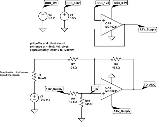
Anyway, I'm concerned with pH 4-10 (just enough to sneak in standard pH solutions for calibration). I've add enough gain so that 4-10pH @ 40C almost hits the entire span (which is plenty more resolution that I really need).
What circuitlab can't really help with (or at least I don't know to to do it) is handling noise and instability. How do you think this would hold up in the real world? I figure I'll need an RC filter on the output and I'm just reading up on those. Like the description says, if it takes 2 minutes to go from 0 to 1.8V that's actually Speedy Gonzalas territory in this application.
So, is this simply not going to work the way I think or is there modifications I can do to make it work (better)?
Thanks!
simulate this circuit – Schematic created using CircuitLab
P.S. BBB = BeagleBone Black. 3.3v supply, 1.8v ADC and 1.8v analog supply limited to about 10mV which is why the voltage follower/buffer to power the opamps.
Edit: Spotted a tip about matching input resistances between the two inputs. Reduced R7 and R8 to 1k and 4.3k to get 811 ohms on - and 779 ohms on +. Should I add the extra 30ish ohms to the + input or do you think the 30ish ohms makes no difference?