1

I'm building a circuit to detect whether an AC line has been turned on by a triac. I'd like to use an optoisolator to detect when the AC is on, and send a 3.3v signal back to my microcontroller.

What's the difference between an optoisolator with Logic output and Transistor/Photovoltaic output? The logic output optoisolator I've found is an MID400, which is described as a power line monitor and costs a lot per sensor. The cheaper option is a photovoltaic output, TCLT1600 with AC input.

Topher
  • 29
  • 4
  • Possible duplicate of [What are the differences between optoisolator output styles?](https://electronics.stackexchange.com/questions/187706/what-are-the-differences-between-optoisolator-output-styles) – CL. Sep 06 '17 at 07:05
  • You got confused by DigiKey's categorization, which groups two types. – CL. Sep 06 '17 at 07:07
  • @CL, can you explain more about categorization/2 types? I've already looked at the question you posted, and it didn't address what I'm asking. – Topher Sep 06 '17 at 15:34
  • The TCLT1600 does not have a photovoltaic output. – CL. Sep 06 '17 at 16:25
  • Ok. So the TCLT1600 is a standard transistor optoisolator, with AC input. Thanks for clarifying this point, @CL! My question is what's the difference between the 2 chips, could you help me with that? It seems like I can use the cheaper transistor optoisolator with AC input in order to accomplish my goal, but I'm left wondering what the added benefit of the more expensive logic output optoisolator is. – Topher Sep 06 '17 at 16:49

1 Answers1

0

With a phototransistor optocoupler, the output current is roughly proportional to the input current, and during the zero crossings of the AC input, the output is off.

As shown in application note AN-3007, the MID400 has much higher amplification (resulting in an essentially digital output), and is slower:

MID400 circuit schematic

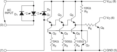
The Photodiode, D3, is coupled into a high gain 3 stage emitter follower current amplifier (Q1Q3Q5) driving into an output transistor Q8. The emitter follower loads are comprised of constant current circuits formed by Q2, R2, Q4, R3, Q6, and R4. Constant current level in these devices is established by the constant voltage source formed by the base emitter voltage of Q7 and R5.
[…]
Switching time of the amplifier is intentionally designed to be slow, so that the MID400 only responds to an absence of input signal over a few milliseconds, and not during the short zero-crossing period of the AC input voltage waveform.

So you would use the MID400 if you needed more output current without loading the AC input too much, or if you did not want to smooth the output signal in your own circuit or in software.

CL.
  • 18,161
  • 5
  • 40
  • 67