0

I've been working on a circuit to dim a Shop Light that according the manufacturer is 0-10V dimmable.

Built into the light is an LED power supply that provides two wires, a purple DIM+ and grey DIM-. The power supply appears to source a constant 0.1mA current on these wires, and the measured the voltage between them is 10V.

When the wires are unconnected or connected with a resistor >= 100KΩ, the light runs at maximum brightness. Shorting them or connecting them with a resistor <= 270Ω causes the light to run at minimum brightness.

I want to control this light with an ESP32 microcontroller, so I looked at digital potentiometers. The idea was to make a rheostat to control the resistance between DIM+ and DIM-.

When I was looking at digital potentiometers a unifying theme for almost all of them is that the maximum voltage on the rheostat pins tends to be right around Vdd, which in my case is 3.3V.

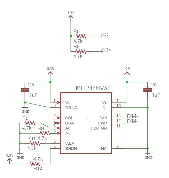
Since I need the rheostat to be able to handle 10V, I purchased a Microchip Dual Rail Digital Potentiometer. This chip has dual supplies, so the IC itself can be driven with 3.3V, and the rheostat can be driven with a separately supplied voltage. Here's the circuit I came up with (using a separate 12V supply for the pot's V+):

enter image description here

After hooking this up and writing the ESP32 software everything is working. The light dims. But here's the problem:

When I completely disconnect the 12V external supply from V+/V- (pin 14 and pin 10 are NC/floating), it still works. The rheostat measures the correct resistance depending on the value I store in the wiper register and no smoke is observed.

My question then is - why is this working? The follow up is do I really need a dual-supply potentiometer or could I get something cheaper?

For what it's worth, I can see connecting something like 20-30 of these lights together, so current could go up to 2-3mA.
par
  • 275
  • 6
  • 15
  • 2
    Why is it working? Clamp diodes allowing leakage to the rails. Either from the digital section or from your 0-10V lines. In either case it is not recommended. What voltage is across the entire digital wiper in this situation. – Passerby Sep 04 '17 at 23:19

1 Answers1

1

My question then is - why is this working? The follow up is do I really need a dual-supply potentiometer or could I get something cheaper?

I can't answer the first part but can help with the second.

enter image description here

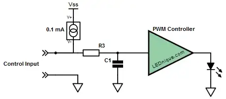
Figure 1. Probable innards of OP's dimmer control.

I think your diagnosis of the PSU input is correct and that the PSU control circuit is as shown in Figure 1. Please see my answer to 0-10V Digital Rheostat for LED Dimmer? for a full explanation of the operation and control of these power supplies using potentiometers, 0 - 10 V control signals or, most appropriate in your case, simple PWM control. (The PWM gets filtered by the low-pass filter R3 and C1 to give the 0 - 10 V control signal.)

Note that with a suitable drive transistor you can drive a very large number of dimmers in parallel. No need for digital or analog pots.

Transistor
  • 168,990
  • 12
  • 186
  • 385
  • Thank you for your answer on this and my other question. I'm sorry but I guess I didn't follow. All I need to build is the dimmer. Are you saying I can just connect DIM+ and DIM- to an NPN transistor and control the base using PWM on a GPIO? What frequency do you run the PWM at? – par Sep 04 '17 at 23:25
  • Do you have by any chance a schematic for a real circuit (with part #'s/values)? I'll try to build it on my own regardless but it would be helpful to see how to do it right. – par Sep 04 '17 at 23:42
  • Yes, see Figure 3 in my answer on the linked question. – Transistor Sep 05 '17 at 06:09
  • Thank you. I hooked exactly as shown on your Figure 3 (assuming R3 and C1 are internal to the power supply which seems to be what you're saying) and ran 8KHz PWM over 0-100% duty cycle. The measured voltage when the transistor is off is 10V as expected, but it varies down to no lower than ~6V and the dimming is inconsistent. Maybe the driver doesn't know how to deal with PWM. Unfortunately there are no docs on the power supply that I can find. Again, thank you very much for your replies, outside of this website I wouldn't know who to ask. – par Sep 05 '17 at 06:22
  • It should work. Check that you have your grounds connected together properly. Edit your question to reference my answer and post a schematic of your interface and a photo if you think it might help. – Transistor Sep 05 '17 at 06:27
  • Are you sure that any kind of PWM is required at all? I would just try feeding the DIM+ and DIM- with a variable 0-10VDC supply and see what happens. – R Drast Sep 05 '17 at 12:44
  • DIM+ and DIM- already have a voltage across them at 10V supplied by the power supply at 0.1mA, so whatever I connect to it has to sink that current. I'll post a schematic and photos tonight. – par Sep 05 '17 at 14:28
  • @Transistor I must have had something connected improperly. It's working now. I'm using a `Vb`=3.3V microcontroller and a PN2222A transistor which has a `ß` of 35 when `Ic`=0.1mA & `Vce`=10V (per the [datasheet](https://cdn-shop.adafruit.com/datasheets/PN2222A.pdf)). `Ib`=`Ic/ß`=3µA,`Vbe`~=0.7 so I calculated `Rb=(Vin-Vbe)/Ib` as 910KΩ. That's a much larger base resistor than the 1KΩ you used in your previous answer's Figure 3 diagram. A 1KΩ resistor works, but should I stick closer to the 910KΩ that will switch with the least base current? – par Sep 07 '17 at 06:26
  • 1
    Congratulations. Just note that when you're driving a transistor into saturation that you should give a base current two or three times that required by the linear gain calculations. This insures that it will work with the variation from device to device, variations due to temperature effects and load variations. For your low current application these risks are low. Don't forget to accept the answer if it's solved your problem (although maybe not the original digital pot question). – Transistor Sep 07 '17 at 07:15